

Special-shaped flange and foundation pit steel supporting structure using same
A special-shaped flange and steel support technology, which is applied in basic structure engineering, building construction, construction, etc., can solve problems such as unsuitable thick steel pipes, increased difficulty in hoisting, and small rigidity of a single root, etc., to improve corrosion resistance, Simple construction and assembly, and the effect of improving torsional strength
- Summary
- Abstract
- Description
- Claims
- Application Information
AI Technical Summary
Problems solved by technology
Method used
Image

Examples
Embodiment 1
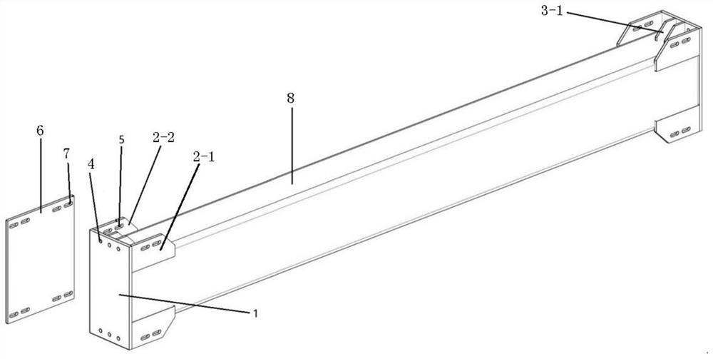
[0075] As a preferred embodiment of the special-shaped flange of the present invention, the left limiting part is two first wing plates arranged at the upper and lower ends of the left side of the end plate, and the two first wing plates are connected to the end plate. Plate vertical intersection setting;
[0076] The right limiting part is two second wing plates arranged at the upper and lower ends of the right side of the end plate, and the two second wing plates are vertically intersected with the end plate.
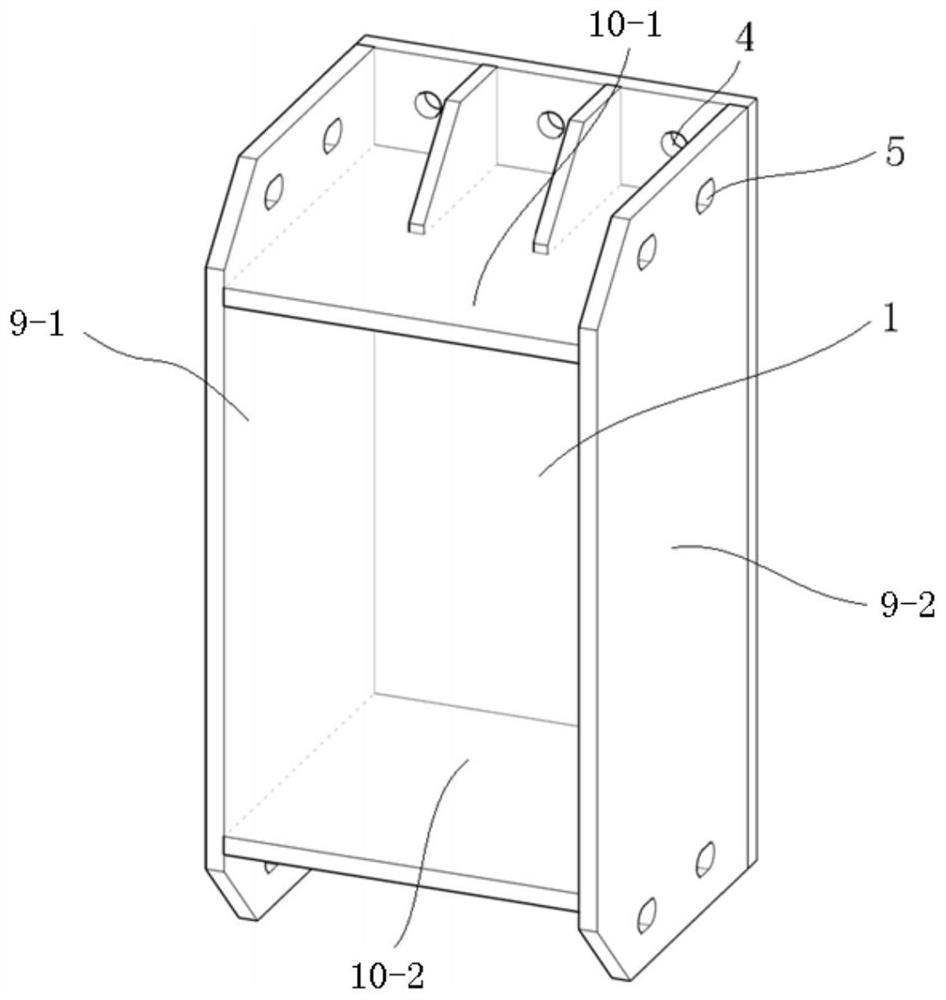
[0077] The upper limit part is a first ribbed plate arranged on the upper part of the end plate, and the first ribbed plate is vertically intersected with the end plate;
[0078] The lower limiting part is a second ribbed rib arranged at the lower part of the end plate, and the second ribbed rib is vertically intersected with the end plate.
[0079] Preferably, the end plate is a rectangular steel plate; the outer edge of the first wing plate is flush with the left e...
Embodiment 2
[0083] As another preferred embodiment of the special-shaped flange of the present invention, the left limiting part is a first side plate arranged on the left side of the end plate, and the first side plate is vertically intersected with the end plate ;
[0084] The right limiting part is a second side plate arranged on the right side of the end plate, and the second side plate is vertically intersected with the end plate.
[0085] The upper limit portion is an upper bottom plate arranged on the upper part of the end plate, and the upper bottom plate is vertically intersected with the end plate;
[0086] The lower limiting part is a lower bottom plate arranged at the lower part of the end plate, and the lower bottom plate is vertically intersected with the end plate.
[0087] Preferably, the end plate is a rectangular steel plate; the outer edge of the first side plate is flush with the left edge of the rectangular steel plate; the outer edge of the second side plate is flus...
PUM
 Abstract
Description
Claims
Application Information