
Eureka
For R&D, Eureka makes reading and utilizing patents & technical documents easy.
Eureka AIR
Designed for self-driven R&D workflows. Generate viable solutions, solve complex R&D challenges, empower your innovation with AI.

Eureka Materials
Designed for material experts only. Revolutionize your material R&D, from search, analyze, to developing new materials.

TechResearch
Generate reliable direction feasibility study reports for your R&D in just a few steps.

TechSeek
Discover and master advanced knowledge NOW. Basics, ideas, possibilities, all at once.

TechMind
As an expert in R&D Theories, TechMind can generates customized viable solutions instantly.

TechRisk
Analyze your overall solution with one click, know your potential R&D risks in advance.

TechMonitor
Get weekly tech updates, stay abreast of the latest tech innovations and key insights.
Low-permeability strong-adsorbability coal body heat injection equipment
A technology with strong adsorption and low permeability, applied in mining equipment, gas discharge, safety devices, etc., can solve the problems of long gas extraction time, low extraction efficiency, and coal seam gas control effect not reaching the expected goal.
- Summary
- Abstract
- Description
- Claims
- Application Information
AI Technical Summary
Problems solved by technology
Method used
Image

Examples
Embodiment 1
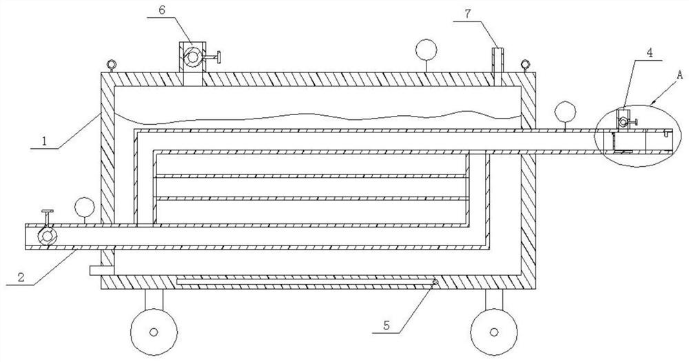
[0021] Embodiment one is basically as attached figure 1 , 2 Shown: as figure 1 The heat injection equipment for low-permeability and strong-absorptive coal body shown includes a heating box 1, a delivery pipe 2, a delivery pipe 3 and a pressure relief extraction pipe 4. The top of the heating box 1 is welded with lifting rings on the left and right sides, and the bottom of the heating box 1 Rollers are installed on the lower surface, and a heater is installed in the bottom of the heating box 1. The heater can be a U-shaped heating tube 5, and the heating tube 5 is connected to the power supply through a wire; the top of the heating box 1 has a water injection port 6 and an exhaust port 7. ; There is a cavity (not shown in the figure) in the side wall of the heating box 1, and a thermal insulation material, such as an asbestos layer, is placed in the cavity.
[0022] Conveying pipe 2 runs through heating box 1, and the left end of conveying pipe 3 is connected with the air ou...
Embodiment 2
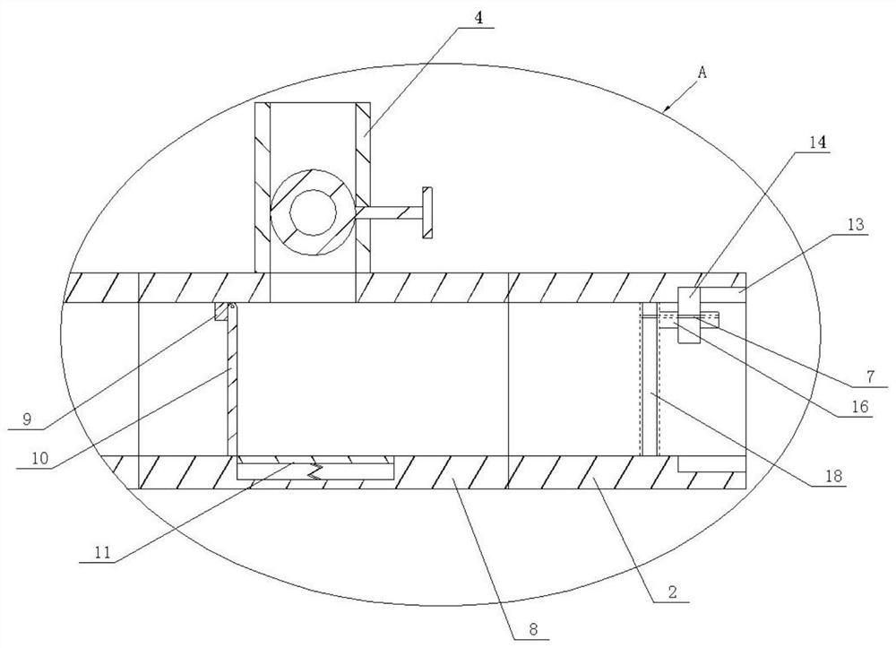
[0027] On the basis of Example 1, as figure 2 As shown, there is a groove in the square hole section 8 of the conveying pipe 2, and the groove is arranged opposite to the pressure relief extraction pipe 4, and a limit mechanism is arranged in the groove, and the limit mechanism includes a tension spring and a limit plate 11. The position plate 11 is slidably arranged in the groove, and the limit plate 11 is connected with the bottom of the groove by an extension spring, that is, the lower end of the extension spring is welded to the bottom of the groove, and the upper end of the extension spring is welded to the lower surface of the limit plate 11. When the negative pressure pump sucks the gas, the limit plate 11 slides upward under the negative pressure and contacts the one-way valve plate 10, thereby preventing the one-way valve plate 10 from turning counterclockwise under negative pressure to prevent gas from entering the heating box 1 .
Embodiment 3
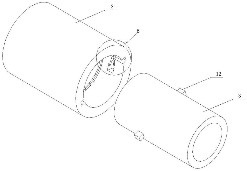
[0029] On the basis of embodiment one or embodiment two, such as image 3 As shown, the transmission pipe 3 welds some booster blocks 12 (only two are shown in the figure) in the circumferential direction of its outer wall, as Figure 4 As shown, the inner wall of the right end of the delivery pipe 2 is provided with an annular groove and a number of chute 13 and arc groove 14 matched with the booster block 12, the annular groove is used to accommodate the gasket 15, and the two ends of the gasket 15 are connected to the ring groove. The side walls are close to each other, and the outer wall of the gasket 15 leaves a distance from the bottom of the annular groove.
[0030]The chute 13 communicates with the arc groove 14, and the left side wall of the arc groove 14 is obliquely provided with a channel 16 connected to the annular groove, and the right side wall of the arc groove 14 is also provided with a channel 16, and the channel 16 is slidably provided with a booster Bar 17...
PUM
 Abstract
Description
Claims
Application Information
 - R&D Engineer
- R&D Manager
- IP Professional
- Industry Leading Data Capabilities
- Powerful AI technology
- Patent DNA Extraction
Browse by: Latest US Patents, China's latest patents, Technical Efficacy Thesaurus, Application Domain, Technology Topic, Popular Technical Reports.
© 2024 PatSnap. All rights reserved.Legal|Privacy policy|Modern Slavery Act Transparency Statement|Sitemap|About US| Contact US: help@patsnap.com