
Gas supercharging device for carbon dioxide flooding

A technology of gas pressurization and carbon dioxide, applied in other gas emission reduction technologies, container structure installation devices, gas/liquid distribution and storage, etc., can solve the problem of affecting carbon dioxide displacement effect, lack of carbon dioxide gas pressurization function, and reduce work Solve problems such as the labor intensity of mobile devices, achieve reasonable and reliable structure, realize the effect, and achieve the effect of adjustment

Inactive Publication Date: 2021-11-02
柏宗宪
View PDF9 Cites 5 Cited by
  • Summary
  • Abstract
  • Description
  • Claims
  • Application Information

AI Technical Summary

Problems solved by technology

[0003] In the patent document "CN109469464A A carbon dioxide injection device for carbon dioxide flooding", it continuously injects carbon dioxide gas while ensuring stable and orderly injection of carbon dioxide gas to improve the continuous supply efficiency of carbon dioxide gas. The push rod pushes the support seat to adjust the rolling wheel to push up the fixed seat, which is convenient for workers to push and move the device, which greatly reduces the labor intensity of the worker's mobile device. However, it lacks the function of carbon dioxide gas pressurization. When carbon dioxide gas contacts crude oil , the lower pressure is not enough to form miscible phases, affecting the CO2 displacement effect
There is still no gas boosting device for carbon dioxide flooding with reasonable and reliable structure, temperature regulation function and carbon dioxide high-efficiency boosting function.

Method used


Image

  • Gas supercharging device for carbon dioxide flooding
  • Gas supercharging device for carbon dioxide flooding
  • Gas supercharging device for carbon dioxide flooding

Examples


Embodiment Construction

[0031] In order to enable those skilled in the art to better understand the solution of the present application, the technical solution in the embodiment of the application will be clearly and completely described below in conjunction with the accompanying drawings in the embodiment of the application. Obviously, the described embodiment is only It is an embodiment of a part of the application, but not all of the embodiments. Based on the embodiments in this application, all other embodiments obtained by persons of ordinary skill in the art without making creative efforts shall fall within the scope of protection of this application.

[0032] It should be noted that the terms "first" and "second" in the specification and claims of the present application and the above drawings are used to distinguish similar objects, but not necessarily used to describe a specific sequence or sequence. It should be understood that the data so used may be interchanged under appropriate circumst...


PUM


Abstract

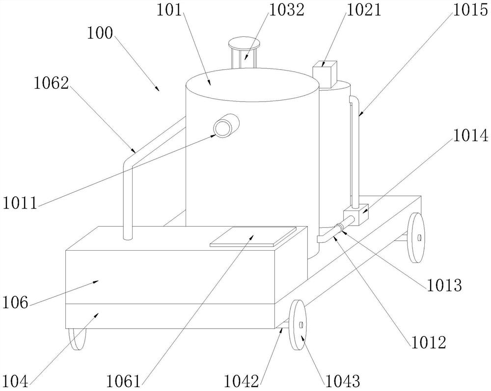
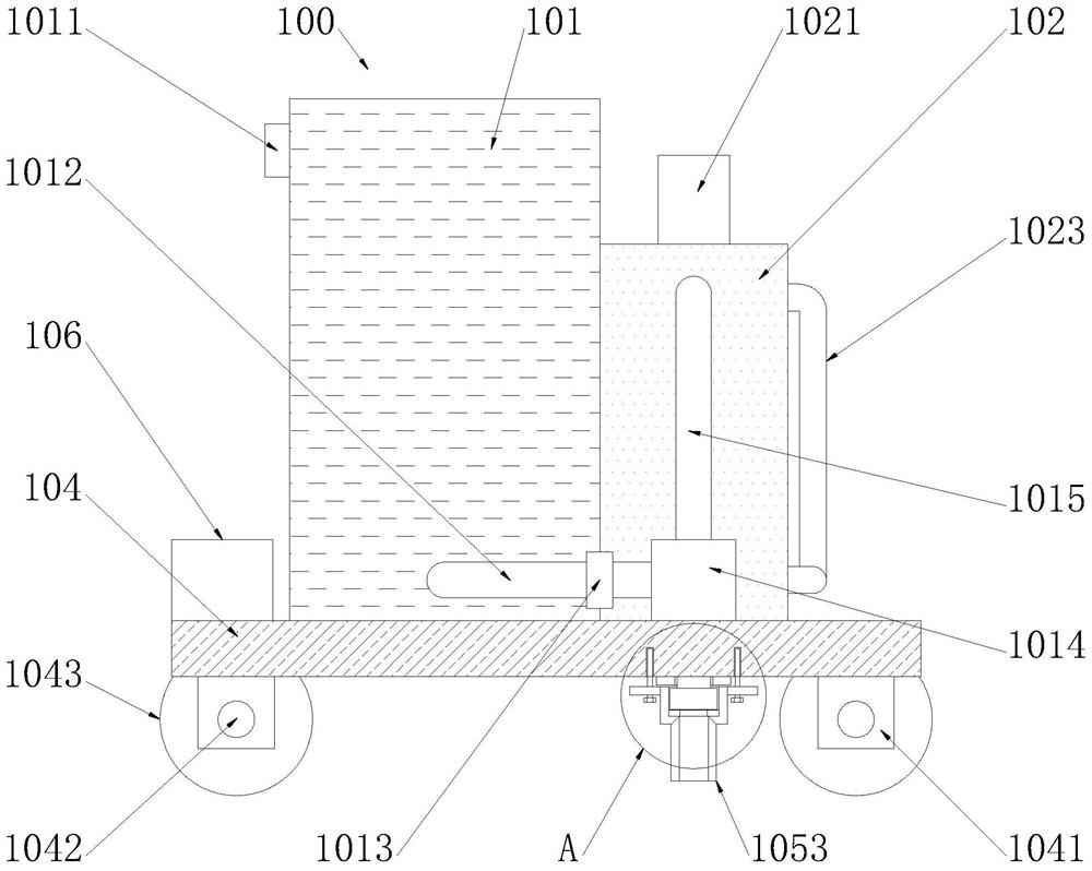
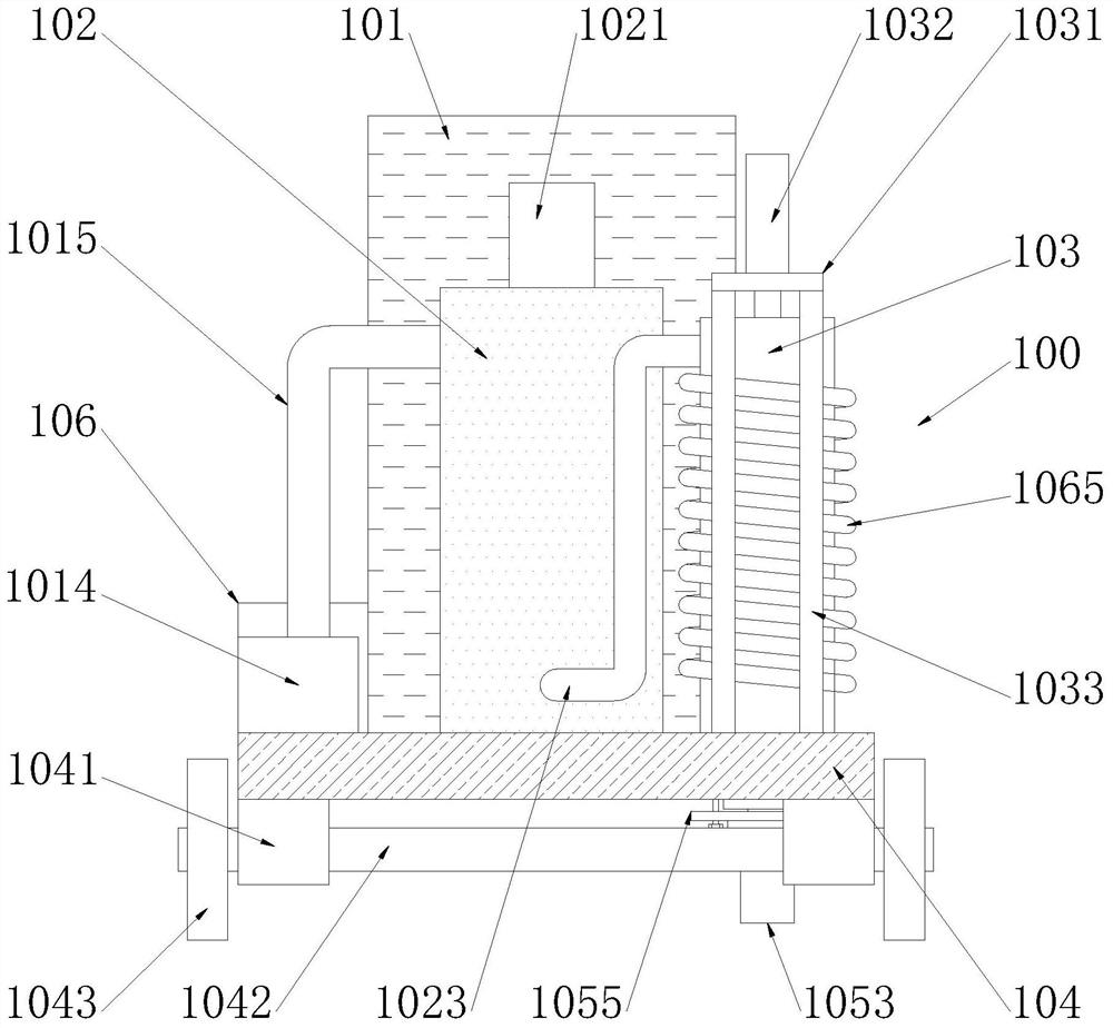
The invention discloses a gas supercharging device for carbon dioxide flooding. The device comprises a tank body, a drainage pipe, a gas outlet pipe, an adjusting valve, a booster pump, a gas inlet pipe, a first barrel body, a motor, a spiral shaft, a flow guide pipe, a second barrel body, a top plate, a hydraulic cylinder, supporting legs, a pressing plate, a connecting rod, a limiting rod, a piston, a sealing ring, a supporting plate, a bearing seat, a rotating shaft, a roller, a washer, a fixed pipe, a connecting pipe, a sleeve, a conveying pipe, a gasket, a convex plate, a bolt, a box body, a box cover, a water outlet pipe, a water inlet pipe, a water pump, a circulating pipe, a separator plate and a diversion port. The device has the beneficial effects that the tank body is adopted for storing carbon dioxide, carbon dioxide gas can be compressed while carbon dioxide is conveyed, the pressurization effect of carbon dioxide is improved, the effect of mixing the carbon dioxide with crude oil is improved by adopting multi-stage gas compression, heat dissipation of the surface of the barrel body can be implemented, temperature adjustment is achieved, and adjustment on pressure and temperature in the carbon dioxide gas conveying process is facilitated.

Description

technical field [0001] The invention relates to a gas booster for carbon dioxide flooding, in particular to a gas booster for carbon dioxide flooding, and belongs to the technical field of carbon dioxide flooding applications. Background technique [0002] Carbon dioxide flooding technology is a technology that injects carbon dioxide into the oil layer to increase the oil recovery rate of the oil field. When carbon dioxide and formation crude oil first contact, they cannot form miscible phases, but under the conditions of suitable pressure, temperature and crude oil components, carbon dioxide can form miscible phases. At the front, the supercritical fluid will extract heavier hydrocarbons from the crude oil, and continuously concentrate the gas that displaces the front, and the carbon dioxide and crude oil will become miscible liquids, forming a single liquid phase, so that the Formation crude oil is displaced to the production well, which has a viscosity-reducing effect: ca...

Claims


Application Information

Patent Timeline
IPC IPC(8): F17C1/00F17C13/00F17C13/08F17D1/07F17D3/01E21B43/16
CPCF17C1/00F17C13/00F17C13/08F17D1/07F17D3/01E21B43/168F17C2205/0161F17C2221/013F17C2223/0123F17C2227/0157F17C2227/0348Y02P90/70
Inventor 柏宗宪
Owner 柏宗宪
Learn More