
Composite anti-riot kinetic energy projectile with delay boosting function

A compound and boosting technology, applied in the field of anti-riot bombs, can solve the problems of excessive damage, insufficient long-range performance, short-range power and long-distance performance, and achieve the effect of making up for the speed drop and solving the effect of short-distance excessive power

Active Publication Date: 2021-11-02
ENG UNIV OF THE CHINESE PEOPLES ARMED POLICE FORCE
View PDF5 Cites 0 Cited by
  • Summary
  • Abstract
  • Description
  • Claims
  • Application Information

AI Technical Summary

Problems solved by technology

Therefore, the composite anti-riot kinetic energy projectile solves the problem of excessive short-range power and insufficient long-distance performance of the active anti-riot kinetic energy projectile to a certain extent. Optimizing the material of the bullet to obtain the ideal impact response characteristics of the bullet is difficult to fundamentally solve the problem of excessive power at close range, because even if the bullet has extreme compression deformation, due to the high exit velocity of the bullet, it is not enough to completely avoid damage to living targets. Excessive damage, so it is necessary to further optimize the design of the projectile structure, so that the problem of "too much power at close range and insufficient performance at long range" can be better solved, and at the same time effectively solve the problem of single terminal effect of existing anti-riot kinetic energy projectiles

Method used


Image

  • Composite anti-riot kinetic energy projectile with delay boosting function
  • Composite anti-riot kinetic energy projectile with delay boosting function
  • Composite anti-riot kinetic energy projectile with delay boosting function

Examples


Embodiment Construction

[0027] The following will clearly and completely describe the technical solutions in the embodiments of the present invention with reference to the accompanying drawings in the embodiments of the present invention. Obviously, the described embodiments are only some, not all, embodiments of the present invention. Based on the embodiments of the present invention, all other embodiments obtained by persons of ordinary skill in the art without making creative efforts belong to the protection scope of the present invention.

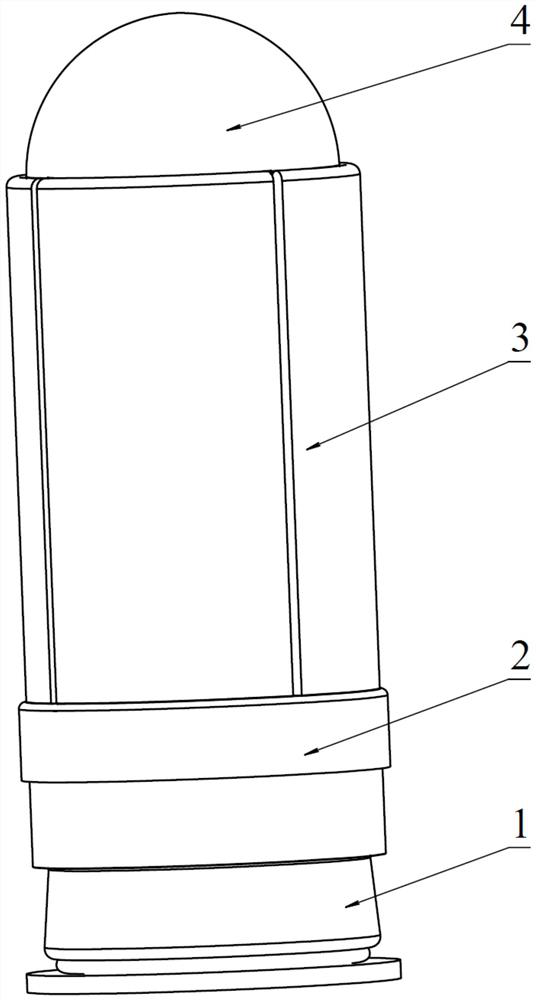
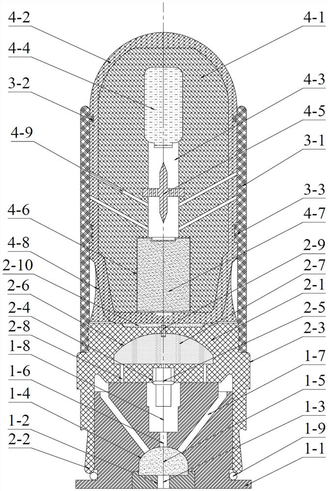
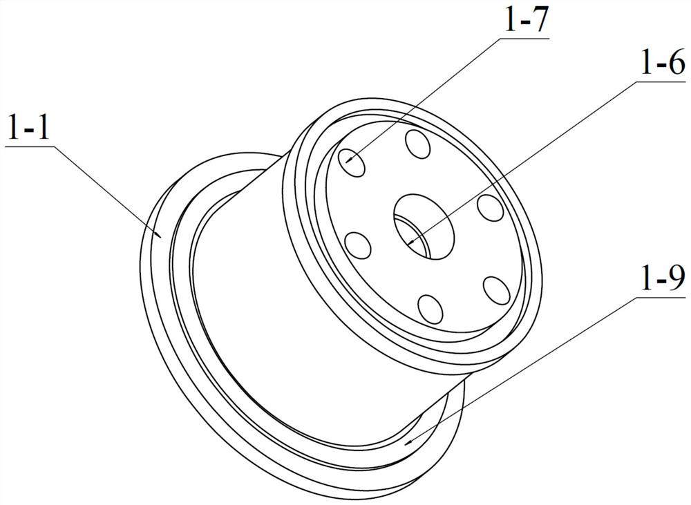
[0028] see Figure 1-6 , the present invention provides a technical solution: a composite anti-riot kinetic energy projectile with a delayed boost function, comprising a launch assembly 1, a projectile body assembly 2, a shield assembly 3 and a warhead assembly 4, characterized in that:

[0029] The launch assembly 1 includes a launch cartridge 1-1, a primer hole 1-2, a primer 1-3, a high pressure chamber 1-4, a propellant 1-5, an axial fire hole 1-6, and an o...


PUM


Abstract

The invention discloses a composite anti-riot kinetic energy projectile with a delay boosting function. The composite anti-riot kinetic energy projectile comprises a firing assembly, a projectile body assembly, a guard plate assembly and a projectile head assembly, wherein the projectile body assembly sleeves the firing assembly, the projectile head assembly adheres to the projectile body assembly, and the guard plate assembly wraps the projectile head assembly and the projectile body assembly; two stages of delay boosting mechanisms are arranged in the projectile body assembly, the first-stage delay boosting mechanism achieves primary boosting of the projectile body assembly and the projectile head assembly, the second-stage delay boosting mechanism achieves separation of the projectile head assembly and the projectile body assembly and secondary boosting of the projectile head assembly, and a high-pressure gas cylinder and a stimulant loading cavity are arranged in the projectile head assembly. The projectile is compressed to drive a firing pin to achieve gas cylinder blasting and stimulation powder spraying, the short-distance impact speed is low, excessive damage is not prone to be caused, primary boosting acceleration is carried out in the medium distance, and secondary boosting acceleration is carried out in the long distance, so that the problems that short-distance power is too large, and long-distance efficiency is insufficient are effectively solved, and multiple effects of kinetic energy, detonation and lacrimation and dispersion are achieved at the end point.

Description

technical field [0001] The invention relates to the technical field of anti-riot bombs, in particular to a composite anti-riot kinetic energy bomb with a delay boost function. Background technique [0002] As the mainstream anti-riot kinetic energy bombs in service, rubber bullets and bag bombs are gradually replaced by a new generation of composite anti-riot kinetic energy bombs because of their short effective range, poor strike accuracy, and single effect. Composite anti-riot kinetic energy bullets are composed of two materials, soft warhead and hard warhead. Due to different impact speeds at different shooting distances, different impact forces are produced, which forces the warhead to deform to different degrees to dissipate the impact energy. When impacting at short range and high speed, the warhead deforms greatly and dissipates more energy, which can reduce the accidental damage to the target. When impacting at long distance and low speed, the warhead deforms less, d...

Claims


Application Information

Patent Timeline
IPC IPC(8): F42B12/02F42B12/76F42B5/10F42B5/16F42B10/06
CPCF42B12/02F42B12/76F42B5/10F42B5/16F42B10/06
Inventor 汪送马永忠樊向武李阿楠刘星雨贾晓玲
Owner ENG UNIV OF THE CHINESE PEOPLES ARMED POLICE FORCE
Learn More