Variable-temperature strain sensor calibration device and method

A strain sensor and calibration device technology, applied in measurement devices, optical devices, instruments, etc., can solve problems such as the influence of calibration accuracy, the inability of fiber grating strain sensors to calibrate dynamic and static strain at the same time, etc. uniform effect

Active Publication Date: 2021-11-02
NAT INST OF METROLOGY CHINA
View PDF6 Cites 2 Cited by
  • Summary
  • Abstract
  • Description
  • Claims
  • Application Information

AI Technical Summary

Problems solved by technology

[0007] In view of this, the present invention provides a temperature-variable strain sensor calibration device and method to solve the problem that temperature and deflection affect calibration accuracy and that the strain calibration device cannot simultaneously calibrate the dynamic and static strain of the fiber grating strain sensor

Method used


Image

  • Variable-temperature strain sensor calibration device and method

Examples


Embodiment 1

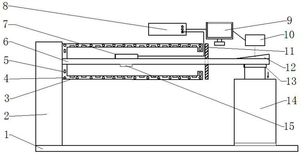
[0026] Refer to attached figure 1 As shown, the present invention provides a temperature-variable strain sensor calibration device, including a base 1, a column 2, a black body furnace 3, a heating wire 4, a cooling plate 5, an equal-strength cantilever beam 6, a fiber grating strain sensor 7, and a fiber grating demodulator System 8, computer 9, precision deflection gauge 10, heat shield 11, deflection compensation block 12, fastener 13, excitation motor 14, thermometer 15; the left end of the base 1 is provided with a column 2, and the column 2 is provided with an equal-strength cantilever Beam 6; Fiber Bragg Grating strain sensor 7 is pasted on the upper surface of equal-strength cantilever beam 6; Fiber Bragg Grating strain sensor 7 is connected to Fiber Bragg Grating demodulation system 8, and Fiber Bragg Grating demodulation system 8 is connected to computer 9; Motor 14, the top end of excitation motor 14 is connected with equal-strength cantilever beam 6; equal-strength...

Embodiment 2

[0028] Example 2: Calibration of Static Strain Sensitivity of Fiber Bragg Grating Strain Sensors

[0029] like figure 1 As shown, the static strain sensitivity calibration method of the fiber grating strain sensor in this embodiment is as follows:

[0030] S1. Glue the fiber grating strain sensor 7 on the upper surface of the equal-strength cantilever beam 6, and establish a connection between the fiber grating strain sensor 7 and the computer 9 through the fiber grating demodulation system 8;

[0031] S2. Control the black body furnace to adjust the internal temperature, use a thermometer to measure the temperature, and adjust to the ideal calibration environment temperature;

[0032] S3. Use the precision deflection gauge 10 to collect the initial position of the deflection compensation block, and send the data to the computer 9, and the computer 9 collects the output wavelength value of the fiber grating strain sensor 7 to obtain the initial value;

[0033] S4. Control th...


PUM


Abstract

The invention discloses a variable-temperature strain sensor calibration device and method, and belongs to the field of testing and metering; the device comprises a stand column, a constant-strength cantilever beam, a fiber bragg grating strain sensor, a fastener, an excitation motor, a blackbody furnace, a deflection compensation block, a fiber bragg grating demodulation system, a computer and a precision deflectometer; wherein the left end of the blackbody furnace is fixedly connected with the stand column, the bottom of the right end of the equal-strength cantilever beam is connected with the excitation motor through a fastener, the left end of the equal-strength cantilever beam penetrates through the blackbody furnace to be connected with the stand column, and the fiber bragg grating strain sensor is pasted and fixed to the upper surface of the equal-strength cantilever beam. The deflection compensation block is arranged above the right end of the equal-strength cantilever beam, the fiber bragg grating demodulation system is connected with the fiber bragg grating strain sensor, the precision deflectometer is arranged at the upper end of the deflection compensation block, and the computer is electrically connected with the fiber bragg grating demodulation system and the precision deflectometer. By means of the device, one-stop calibration of parameters such as dynamic strain, static strain and a strain temperature compensation coefficient is realized.

Description

technical field [0001] The invention relates to the field of test and measurement, in particular to a temperature-variable strain sensor calibration device and method. Background technique [0002] The fiber grating strain sensor is a new type of passive optical sensor based on measuring the strain generated by the force deformation of the object. It has many advantages such as high resolution, intrinsic insulation, low transmission loss, small size, high precision, and easy reuse, so it is widely used in various industries such as health monitoring, aviation and navigation, and petrochemical industry. As a key measuring device and equipment, fiber grating strain sensor is very important to measure its performance accurately. [0003] At present, the calibration of strain sensors mainly adopts the method of bending moment beams, such as equal strength beams. One method is: when calibrating, glue the strain sensor on the beam, load it with weights to deform the moment beam,...

Claims


Application Information

Patent Timeline
Patent Type & Authority Applications(China)
IPC IPC(8): G01B11/16
CPCG01B11/165
Inventor 崔建军侯俊凯陈恺张鹏崔京远
Owner NAT INST OF METROLOGY CHINA
Why Eureka
Try Eureka