Anti-seismic and anti-shear test simulation system and method for tunnel crossing fault zone

A technology of seismic testing and fracture zone, which is applied in the direction of measuring devices, instruments, etc., can solve the problems that are difficult to meet the test, and achieve the effect of convenient assembly, small volume and simple operation steps

Active Publication Date: 2021-11-02
SHANDONG UNIV
View PDF5 Cites 4 Cited by
  • Summary
  • Abstract
  • Description
  • Claims
  • Application Information

AI Technical Summary

Problems solved by technology

The research on the structural failure and disaster reduction measures of tunnels crossing fault zones under the coupling of earthquake action and fault influence has very important engineering significan

Method used


Image

  • Anti-seismic and anti-shear test simulation system and method for tunnel crossing fault zone
  • Anti-seismic and anti-shear test simulation system and method for tunnel crossing fault zone
  • Anti-seismic and anti-shear test simulation system and method for tunnel crossing fault zone

Examples


Embodiment 1

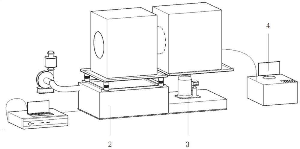
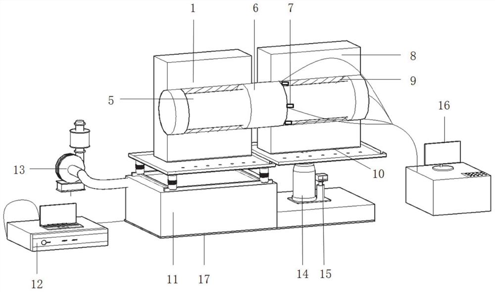
[0028] like figure 1 As shown, a tunnel seismic test system that simulates the fracture belt, including: tomography and tunnel analog unit, vibration unit, lifting unit, and measurement acquisition unit; the break layer and the tunnel analog unit include a first peripheral model sequentially connected, Tunnel model and second perhearten model;

[0029] The vibration unit is connected to the bottom of the first peripheral model for driving the first peripheral model vibration to realize the simulated formation vibration;

[0030] The rising unit is connected to the bottom of the second surrounding rock model for driving the second peripheral rock model to make a uniform elevation movement to achieve analog formation breaks or peristalsis;

[0031] The measurement acquisition unit includes a detecting sensor that detects the strain and vibration data of the tunnel model on one side of the tunnel model.

[0032] As an embodiment, the first peripheral mold is a rectangular structure, ...

Embodiment 2

[0042] The examples also provide a seismic and shear test method that passes through the break tape tunnel, including:

[0043] The vibration system is input to the seismic input wave by the vibration control system, and the vibration table provides vibration action to the first peripheral model to simulate the seismic effect;

[0044] By transmitting the control signal to the displacement by the displacement control device, the movement of the displacement is controlled, which is evenly raised, and the relative mismatch occurred at the tunnel tomography during the simulation of the earthquake;

[0045] The measured strain and vibration data will be output by the data recording apparatus by measuring the strain and vibration data of the tunnel model of the detecting sensor.

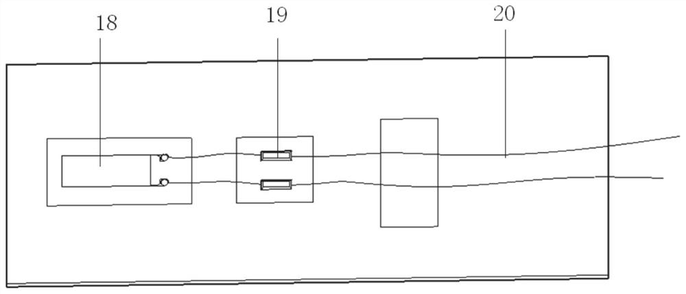
[0046] Specifically, (1) makes a wooden template for a surrounding rock model, placing a iron plate with anchor in the template long width direction, then pouring the light concrete material in the template, ...


PUM


Abstract

The invention provides a tunnel anti-seismic test system and method for simulating fault zone crossing. The tunnel anti-seismic test system comprises a fault and tunnel simulation unit, a vibration unit, a lifting unit and a measurement and acquisition unit; the fault and tunnel simulation unit comprises a first surrounding rock model, a tunnel model and a second surrounding rock model which are connected in sequence; the vibration unit is connected with the bottom of the first surrounding rock model and is used for driving the first surrounding rock model to vibrate so as to simulate stratum vibration; the lifting unit is connected with the bottom of the second surrounding rock model and is used for driving the second surrounding rock model to do constant-speed lifting motion to realize simulation of stratum dislocation or wriggling; the measurement acquisition unit comprises a detection sensor; the detection sensor is mounted on one side of the tunnel model and is used for acquiring strain and vibration data of the tunnel model; and the tunnel mechanical behaviors during earthquake, fault movement and coupling of the earthquake and the fault movement can be studied, and the earthquake and fault movement and the structural failure mechanism are fully revealed.

Description

Technical field [0001] The present disclosure relates to the field of tunnel seismic design techniques, and more particularly to a seismic test simulation system and method for crossing the fault tunnel. Background technique [0002] The statement of this section is merely the background technology information related to the present disclosure, which is not necessarily constituting the prior art. [0003] With the increase in the development of the economy and the increase in population flow, people travel have grown sharply. In recent years, railways and road construction have become more and more important in the country. [0004] With the large-scale construction of the tunnel project, regardless of the urban ceiling or wearing mountains, the tunnel location is often inevitable to cross the fault zone, how to reduce the earthquake effects of the tunnel in the fault and surrounding rocks or wort slip have become a tunnel One of the major topics concerned. The study of structura...

Claims


Application Information

Patent Timeline
IPC IPC(8): G01D21/02
CPCG01D21/02
Inventor 王剑宏贾思佳史璐玉李佳吕高航郭江浩于博翔杨华刘建常洪雷
Owner SHANDONG UNIV
Why Eureka
Try Eureka