
Transmission type micro-scanning optical imaging system suitable for image reconstruction

An optical imaging system and image reconstruction technology, applied in the direction of 2D image generation, image acquisition, image enhancement, etc., can solve the problems of tracking error, tracking lag, error, etc., to eliminate input source error, overcome tracking error, overcome tracking error lag effect

Pending Publication Date: 2021-11-02
CHINA FORESTRY STAR BEIJING TECH INFORMATION CO LTD
View PDF0 Cites 0 Cited by
  • Summary
  • Abstract
  • Description
  • Claims
  • Application Information

AI Technical Summary

Problems solved by technology

[0004] Existing image reconstruction technology uses multiple frames of low-resolution image sequences before and after time to generate a high-resolution image. The problem with this method is that there is a time lag and spatial gap between the multiple frames of low-resolution sequences before and after time. Displacement, there is an error in the input source of image reconstruction, which also leads to the bottleneck of the research on existing image reconstruction technology, and it is difficult to further improve the performance
In addition, in the photoelectric countermeasure system, the target in the image is a high-speed moving target rather than a stationary target, and there is lag and tracking error in the tracking of the photoelectric countermeasure system. In this case, using multiple frames of images before and after the image reconstruction, the error Large, the restoration effect is not good, and it is difficult to obtain the theoretical algorithm effect

Method used


Image

  • Transmission type micro-scanning optical imaging system suitable for image reconstruction
  • Transmission type micro-scanning optical imaging system suitable for image reconstruction
  • Transmission type micro-scanning optical imaging system suitable for image reconstruction

Examples


Embodiment Construction

[0029] The present invention will be further described in detail below with reference to the accompanying drawings.

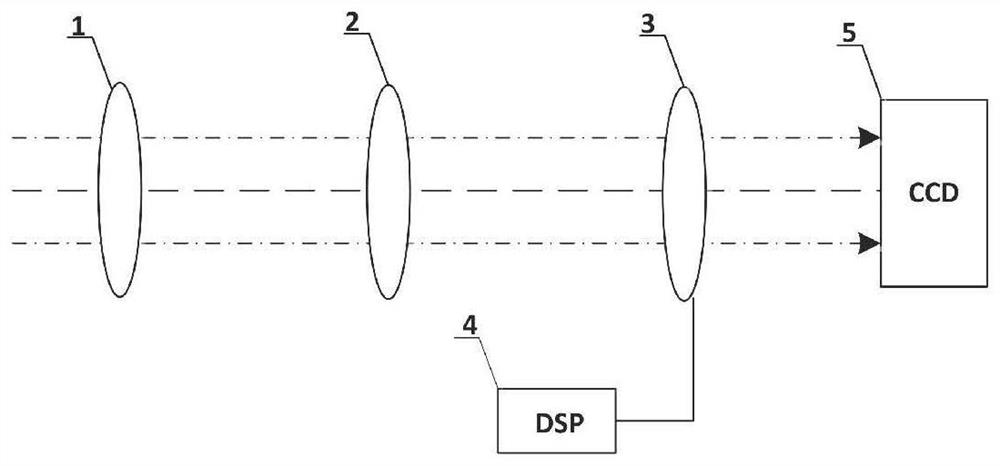
[0030] like figure 1 , The reconstructed image suitable for scanning transmissive micro optical imaging system of the present invention is mounted to the internal photoelectric countermeasure system, the primary optical unit 1, an imaging lens group 2, a two-dimensional dynamic displacement internet decentered lens 3, two dynamic dimensional translation stage controller 4 and the main system CCD5 composition. Specifically: in the main propagation direction of the optical axis of the scanning optical imaging system transmission decline sequentially from left to right is provided with a main optical unit 1, an imaging lens group 2, a two-dimensional dynamic displacement decentered lens platform 3, a main system CCD5.

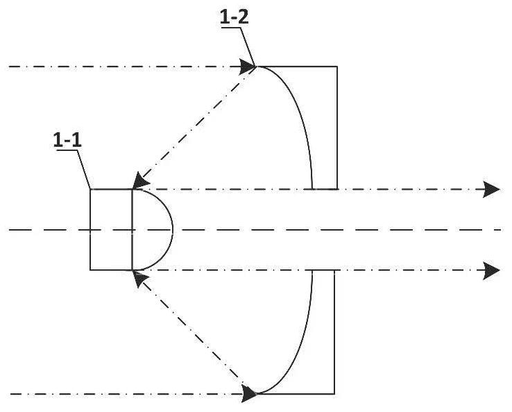
[0031] 1 the main optics and photovoltaic systems against mechanical connection, and is placed with the main optical axis 90, i.e. the main optical un...


PUM


Abstract

The invention discloses a transmission type micro-scanning optical imaging system suitable for image reconstruction, and belongs to the field of photoelectric imaging. The transmission type micro-scanning optical imaging system of the invention is mounted in a photoelectric countermeasure system. The system comprises: a dynamic two-dimensional displacement platform controller, a main optical lens group, an imaging lens group, an eccentric lens dynamic two-dimensional displacement platform and a main system CCD, wherein the main optical lens group, the imaging lens group, the eccentric lens dynamic two-dimensional displacement platform and the main system CCD are sequentially arranged along the propagation direction of a main optical axis; the main optical lens group, the imaging lens group and the eccentric lens dynamic two-dimensional displacement platform are arranged perpendicular to the main optical axis; and the eccentric lens dynamic two-dimensional displacement platform is connected with the dynamic two-dimensional displacement platform controller. Real-time multi-frame images are generated through transmission-type micro-scanning to serve as multi-frame images for image reconstruction processing, and a high-resolution image is generated after fusion, so that the influence caused by a high-speed moving target and a photoelectric countermeasure system tracking error is overcome, and the optimal effect of image reconstruction is achieved.

Description

Technical field [0001] The present invention belongs to the field of photovoltaic technology imaging, particularly to an image reconstruction suitable for scanning transmissive micro optical imaging system. Background technique [0002] With the era of progress and development of technology, the photoelectric warfare equipment and equipment had leaps and bounds, while the photoelectric warfare equipment and the equipment must have picture identification, tracking and processing capabilities. A conventional optical imaging system is limited by design and manufacturing techniques, such optoelectronic devices and equipment against the target in the identification, tracking and processing capability is limited, it is difficult to further follow the pace of development of photovoltaic technology. [0003] Image reconstruction technique has been widely used, can further improve the identification, tracking and processing capacity objectives. Conventional image reconstruction, post imag...

Claims


Application Information

Patent Timeline
Patent Type & Authority Applications(China)
IPC IPC(8): G06T11/00G06T5/50G06T7/292G06T1/00
CPCG06T11/00G06T5/50G06T1/0007G06T7/292G06T2207/10004G06T2207/20221
Inventor 李波宫文彦王生杰黄艳金
Owner CHINA FORESTRY STAR BEIJING TECH INFORMATION CO LTD
Learn More