
High-safety power supply box

A high-safety, power supply box technology, applied in the field of power supply boxes, can solve the problems of overheating damage to the power supply box, poor heat dissipation effect, affecting safe use, etc., to achieve the effect of enhancing the cooling effect, improving the heat dissipation effect, and avoiding overheating damage.

Active Publication Date: 2021-11-02
南通芯锂新能源科技有限公司
View PDF3 Cites 5 Cited by
  • Summary
  • Abstract
  • Description
  • Claims
  • Application Information

AI Technical Summary

Problems solved by technology

The shell of the existing power box is generally all-plastic structure, and the heat generated by the power board and other heating devices is accumulated in the power box and is not easy to dissipate
[0003] In order to improve the heat dissipation effect of the power board, an aluminum radiator is generally installed on the power board, but generally the aluminum radiator and the shell are independent of each other and do not contact each other. The heat of the heating device is conducted to the aluminum radiator and then radiated to the power box. In the air inside, the air temperature rises and transfers heat to the casing, and the casing dissipates the heat. This method has poor heat dissipation effect, and the temperature inside the power supply box is high, resulting in a decrease in power supply reliability. When it is difficult to maintain within the safe range, the power box will be overheated and damaged after working for a long time, which will seriously affect the safe use

Method used


Image

  • High-safety power supply box
  • High-safety power supply box
  • High-safety power supply box

Examples


Embodiment 1

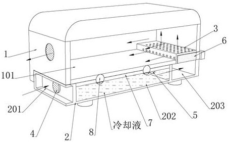
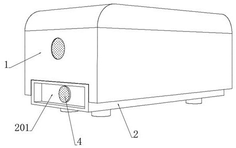
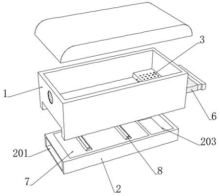
[0042] see Figure 1-6 , a high-safety power supply box, including a power supply box 1, a water cooling box 2 is embedded in the bottom of the power supply box 1, a connecting cavity corresponding to the position of the water cooling box 2 is opened at the bottom of the power supply box 1, and a connecting cavity corresponding to the position of the water cooling box 2 is opened at the bottom of the power supply box 1. The connecting cavity is connected to the hollow cavity, and the hollow cavity is embedded with a flow-through heat-conducting element, which includes a heat-conducting plate 101 and a dispersing wind plate 3 connected to each other. Chamber 202, the left and right ends of the water cooling box 2 are provided with an air induction chamber 201 and an overflow chamber 203 communicating with the water cooling chamber 202 respectively, and a one-way inlet chamber 201 and an overflow chamber 203 are respectively provided at the places where the air induction chamber ...


PUM


Abstract

The invention discloses a high-safety power supply box, which belongs to the technical field of power supply boxs. A water cooling box is arranged at the bottom end of the power supply box, air flows through cooling liquid to be cooled, then is dehumidified through a moisture absorption embedded sheet and flows through a dispersion air plate to be guided into the power supply box, and the heat dissipation effect on the power supply box is improved; a pair of refrigeration pipes connected with a heat conducting plate is arranged in the water cooling box, when the power supply box is at a high temperature, the high temperature is transmitted to an elastic magnetism isolating bag, and matched with gas expanded after heating, the elastic magnetism isolating bag is promoted to expand outwards to weaken the magnetism isolating effect on an upper magnetic sheet, and the upper magnetic sheet repels and pushes a lower half pipe downwards to promote the lower half pipe to be separated from the upper half pipe; the cooling liquid is guided into the refrigeration bag through the exposed drainage pipe, saltpeter particles absorb heat and are cooled when encountering water, on one hand, low temperature is directly transmitted to the power supply box through the heat conducting plate, on the other hand, the low temperature is transmitted to the cooling liquid, the refrigeration effect of the water cooling box is enhanced, air is further cooled, and the power supply box is effectively prevented from being damaged due to overheating.

Description

technical field [0001] The invention relates to the technical field of power boxes, and more specifically, to a high-safety power box. Background technique [0002] The power supply box is a device for storing the power supply, which prevents the power supply from being exposed to damage or theft, and the power supply box can be used to install the power supply in many occasions, expanding the scope of use of the power supply. The shell of the existing power box is generally all-plastic structure, and the heat generated by heat-generating components such as the power board is accumulated in the power box and is difficult to dissipate. [0003] In order to improve the heat dissipation effect of the power board, an aluminum radiator is generally installed on the power board, but generally the aluminum radiator and the shell are independent of each other and do not contact each other. The heat of the heating device is conducted to the aluminum radiator and then radiated to the ...

Claims


Application Information

Patent Timeline
Patent Type & Authority Applications(China)
IPC IPC(8): H05K7/20
CPCH05K7/20281H05K7/20272H05K7/20381H05K7/20327
Inventor 吴词曼
Owner 南通芯锂新能源科技有限公司
Learn More