


Quick Research
Generate reliable direction feasibility study reports for your R&D in just a few steps.

Technical Q&A
Discover and master advanced knowledge NOW. Basics, ideas, possibilities, all at once.

Find Solutions
As an expert in R&D theories, this can generate solutions to your technical problems instantly.

Evaluate Feasibility
Analyze your overall solution with one click, know your potential R&D risks in advance.

Monitor Landscape
Get weekly tech updates, stay abreast of the latest tech innovations and key insights.
Filter cloth flushing device of vacuum belt dehydrator
A washing device, vacuum belt technology, applied in the direction of filtration separation, mobile filter element filter, separation method, etc., can solve the problem of no compressed air adjustment function, etc.
- Summary
- Abstract
- Description
- Claims
- Application Information
AI Technical Summary
Problems solved by technology
Method used
Image

Examples
Embodiment 1
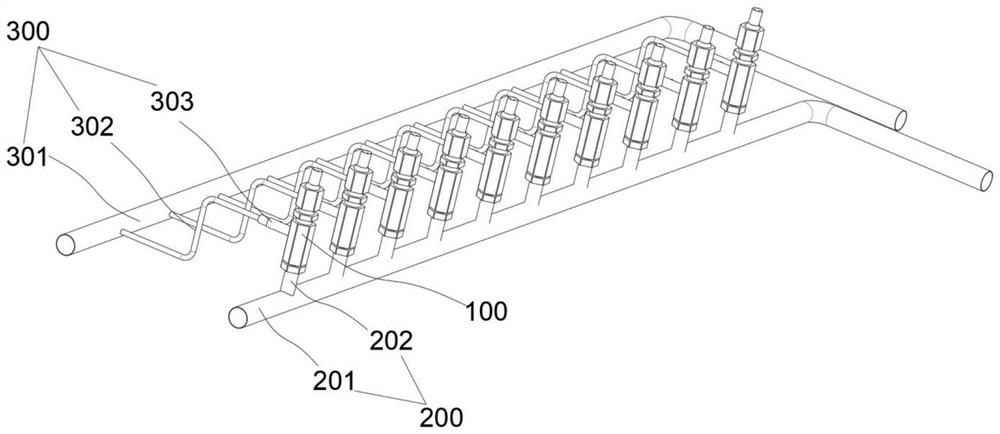
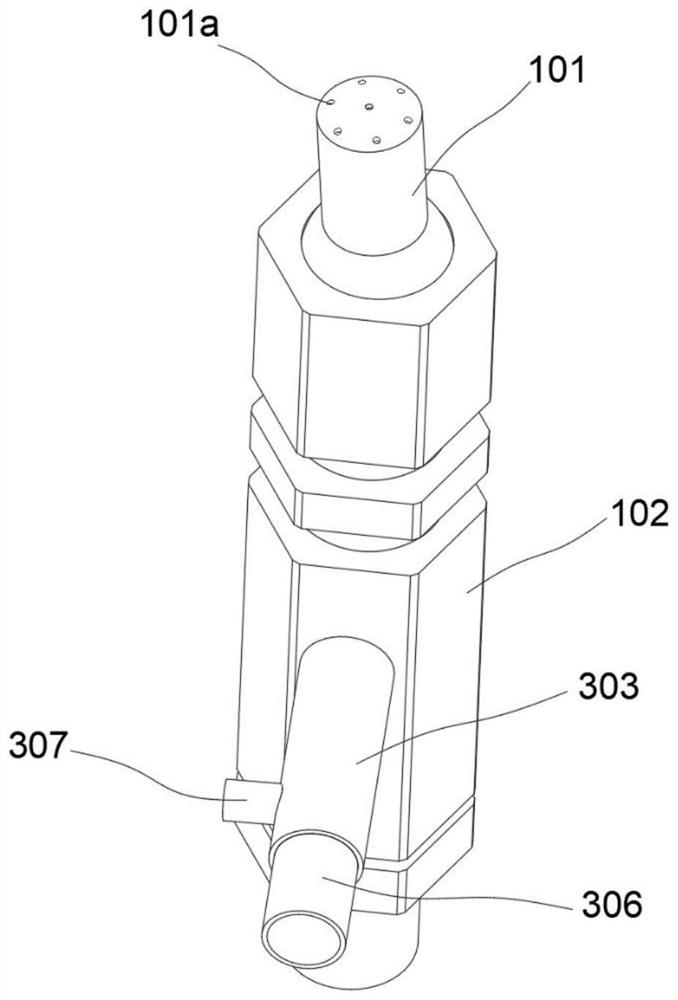
[0031] refer to Figure 1~4 , is the first embodiment of the present invention, which provides a filter cloth washing device for a vacuum belt dehydrator, including a nozzle assembly 100 and a water inlet assembly 200 . The nozzle assembly 100 includes a spray head 101 and a fixed pipe 102 , and the spray head 101 is rotatably connected to one end of the fixed pipe 102 . The water inlet assembly 200 includes a water inlet pipe 201 and a first connecting pipe 202 , one end of the first connecting pipe 202 is connected to the water inlet pipe 201 , and the other end is connected to the end of the fixed pipe 102 away from the shower head 101 . Through the above configuration, the water inlet assembly 200 provides a water source, and the nozzle assembly 100 sprays water on the filter cloth through the rotatable spray head 101 .
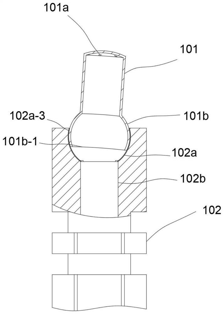
[0032] Further, one end of the nozzle 101 is provided with a plurality of nozzle holes 101a, the other end of the nozzle 101 is provided with a steering...
Embodiment 2
[0039] refer to Figure 5 , is the second embodiment of the present invention, which is based on the previous embodiment, specifically, it also includes an air intake assembly 300 . The air intake assembly 300 includes an air intake pipe 301, a second connecting pipe 302 and an air intake joint 303. One end of the second connecting pipe 302 is connected to the air intake pipe 301, and the other end is connected to the air intake joint 303. The air intake joint 303 is far away from the second connecting pipe 302 One end of is connected with fixed pipe 102. High-pressure gas is passed into the air intake pipe 301, and finally into the nozzle 101 to increase the water pressure.
[0040]Further, an air inlet 303 a is provided in the air inlet joint 303 , and a seal 304 is provided on the side of the air inlet 303 a close to the fixed pipe 102 , and the seal 304 is connected to the inner wall of the fixed pipe 102 through a torsion spring 305 . There are two sealing elements 304,...
PUM
 Abstract
Description
Claims
Application Information
 - R&D Engineer
- R&D Manager
- IP Professional
- Industry Leading Data Capabilities
- Powerful AI technology
- Patent DNA Extraction
Browse by: Latest US Patents, China's latest patents, Technical Efficacy Thesaurus, Application Domain, Technology Topic, Popular Technical Reports.
© 2024 PatSnap. All rights reserved.Legal|Privacy policy|Modern Slavery Act Transparency Statement|Sitemap|About US| Contact US: help@patsnap.com