
Mechanical and electrical integrated cutting device

A cutting device, electromechanical technology, applied in the direction of shearing devices, shearing machine accessories, metal processing machinery parts, etc., can solve the problem of automatic loading and unloading, affecting the working environment of operators, and increasing the workload of operators. Quantity and other issues to achieve the effect of increasing the scope of use, avoiding taking materials, and reducing danger

Pending Publication Date: 2021-11-05
吴汉超
View PDF0 Cites 0 Cited by
  • Summary
  • Abstract
  • Description
  • Claims
  • Application Information

AI Technical Summary

Problems solved by technology

[0003] However, there are some problems in the use of the existing cutting device. The existing cutting device does not have the ability to clamp the material, and the operator needs to manually clamp it during operation. On the platform, it will affect the working environment of the operator, the impurities cannot be collected, and the function of automatic loading and unloading cannot be achieved, which will increase the workload of the operator during use, and will also bring unnecessary danger

Method used


Image

  • Mechanical and electrical integrated cutting device
  • Mechanical and electrical integrated cutting device
  • Mechanical and electrical integrated cutting device

Examples


Embodiment Construction

[0029] The following will clearly and completely describe the technical solutions in the embodiments of the present invention with reference to the accompanying drawings in the embodiments of the present invention. Obviously, the described embodiments are only some, not all, embodiments of the present invention. Based on the embodiments of the present invention, all other embodiments obtained by persons of ordinary skill in the art without making creative efforts belong to the protection scope of the present invention.

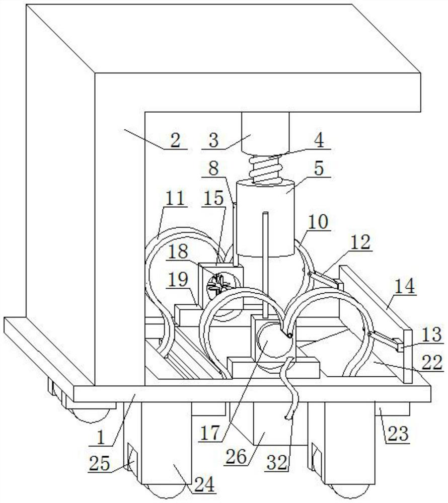
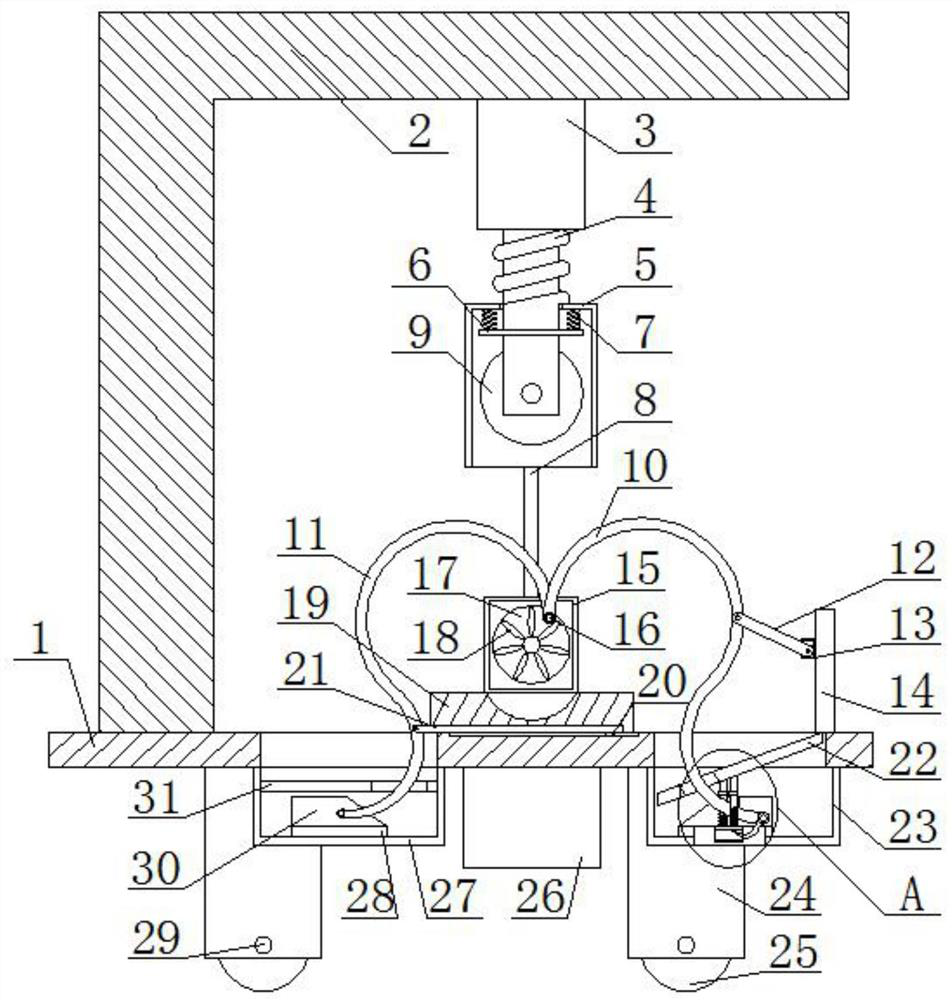
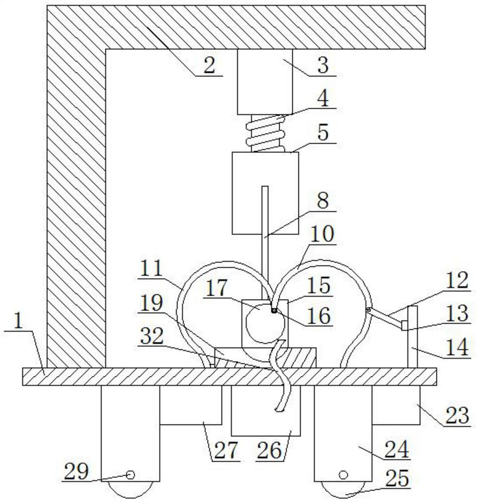
[0030] see Figure 1-5 , the present invention provides a technical solution: a mechatronic cutting device, including a workbench 1, two second fixed rods 29 are arranged at the bottom of the workbench 1, and the front and rear ends of the two second fixed rods 29 are provided with supports Column 24, the top of the support column 24 is fixedly connected to the bottom of the workbench 1, and the bottom of the support column 24 is provided with a second groove, t...


PUM


Abstract

The invention discloses a mechanical and electrical integrated cutting device. The mechanical and electrical integrated cutting device comprises a workbench, wherein an L-shaped plate is fixedly connected to the position, close to the left side, of the top of the workbench, an electric telescopic rod is fixedly connected to the bottom of the L-shaped plate, an electric cutter is fixedly connected to the bottom end of the electric telescopic rod, and a sleeve sleeves the edge of the outer side of the electric telescopic rod; and a fixing disc is fixedly connected to the position, close to the bottom end, of the edge of the outer side of the electric telescopic rod, the fixing disc is located in a sleeve, and a first spring is fixedly connected to the center of the top of the sleeve. Through mutual cooperation of a frame body, blades, a material conveying pipe, a collecting box and other structures, wind energy generated in the cutting process of the electric cutter can drive the blades to rotate, and the blades collect impurities generated in the cutting process, so that the working environment of workers is improved, and the damage of the impurities to bodies of the operators is avoided.

Description

technical field [0001] The invention relates to the technical field of mechatronics, in particular to a mechatronics cutting device. Background technique [0002] Mechatronics technology is a comprehensive technology that organically combines various technologies and comprehensively applies them to practice. Modern automatic production equipment can almost be said to be mechatronics equipment. With the continuous advancement of mechanization, the market The demand for steel is also increasing, making the processing of steel has become very important, including cutting devices. [0003] However, there are some problems in the use of the existing cutting device. The existing cutting device does not have the ability to clamp the material, and the operator needs to manually clamp it during operation. On the platform, it will affect the working environment of the operator, the impurities cannot be collected, and the function of automatic loading and unloading cannot be achieved,...

Claims


Application Information

Patent Timeline
Patent Type & Authority Applications(China)
IPC IPC(8): B23D19/00B23D33/00B23D33/02B23Q11/00
CPCB23D19/00B23D33/00B23D33/02B23Q11/0046
Inventor 吴汉超
Owner 吴汉超
Learn More