Bidirectional beam string structure of rectangular plane

A plane and rectangular technology, applied in the field of two-way string beam structure, can solve the problems of difficult processing and installation of roof units, low stiffness and stability of side string string beams, and achieve the effect of convenient processing and installation, and uniform stiffness

Pending Publication Date: 2021-11-05
BEIJING INST OF ARCHITECTURAL DESIGN
View PDF0 Cites 1 Cited by
  • Summary
  • Abstract
  • Description
  • Claims
  • Application Information

AI Technical Summary

Problems solved by technology

[0009] The object of the present invention is to provide a two-way string beam structure with a rectangular plane, so as to solve the technical problems in the prior art that the processing and installation of roof units are difficult, and the stiffness and stability of the string string beams are low.

Method used


Image

  • Bidirectional beam string structure of rectangular plane
  • Bidirectional beam string structure of rectangular plane
  • Bidirectional beam string structure of rectangular plane

Examples


Embodiment 1

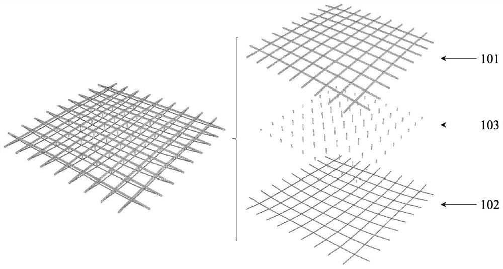
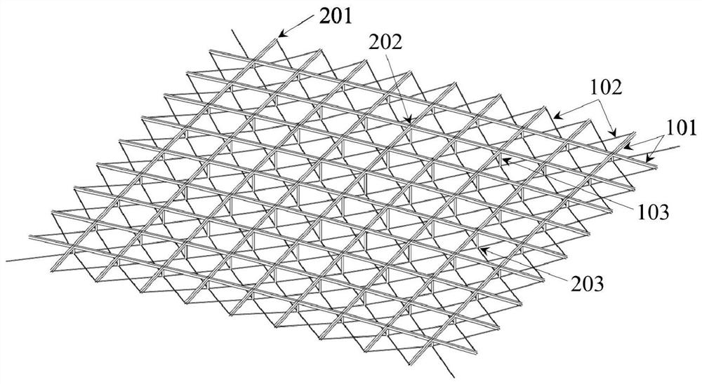
[0038] like figure 2 , image 3 , Figure 4 , Figure 5 , Image 6 and Figure 7 Shown is the first specific implementation of a two-way tension beam structure with a rectangular plane in the present invention. In this embodiment, the two-way tension beam structure is composed of an upper beam system 101, a lower cable system 102 and a strut 103. The horizontal projection of the structure is a square.

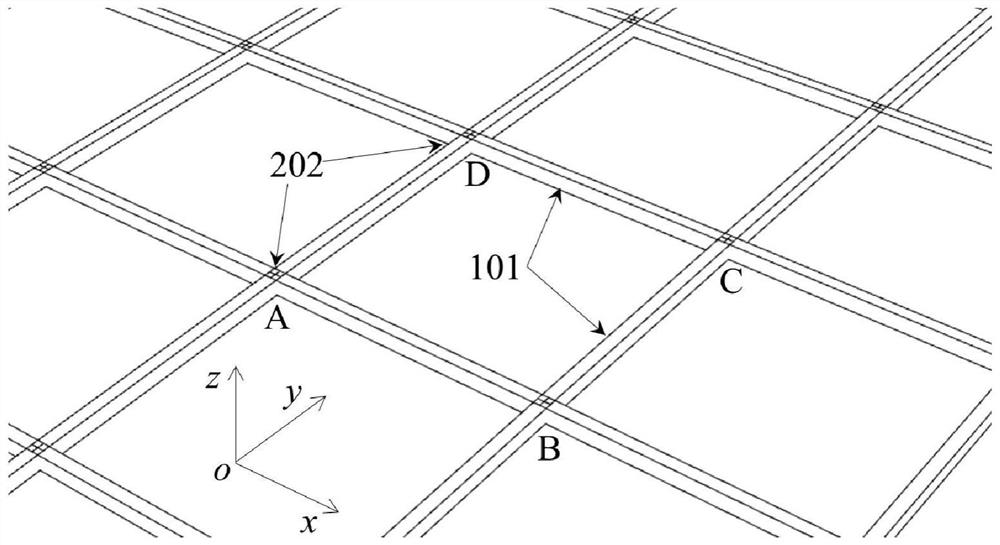
[0039] The upper beam system 101 is composed of two groups of beam systems whose horizontal projection is orthogonal and upright. The horizontal projections of the two groups of beam systems are respectively parallel to the two opposite sides of the structural square plane. The beam end nodes 201 and the upper beam system nodes 202 are located at elliptic paraboloid. A three-dimensional coordinate system is established with the center of the rectangular flat roof as the origin. The x-axis and y-axis of the three-dimensional coordinate system are respectively parallel to ...

Embodiment 2

[0056] like Figure 8 , Figure 9 , Figure 10 , Figure 11 and Figure 12 Shown is a second specific embodiment of a rectangular plane bidirectional stretched beam structure of the present invention. The arrangement of the bidirectional stretched string beam structure in this embodiment is basically the same as that of the first embodiment, and the similarities will not be repeated here. The difference is that the horizontal projection of the structure is a rectangle, and the lower layer cable system 102 adopts the evacuation arrangement, that is, along the diagonal direction parallel to the rectangular plane, braces 103 are arranged below every other row of upper layer beam system nodes 202. and the lower cable tie 102 .


PUM


Abstract

The invention discloses a bidirectional beam string structure of a rectangular plane. The bidirectional beam string structure comprises an upper-layer beam system, a lower-layer cable system and a supporting rod, wherein the upper-layer beam system is formed by connecting two groups of beam systems with orthogonal horizontal projections, an upper-layer beam system node is formed at the intersection of the two groups of beam systems, the horizontal projections of the two groups of beam systems are respectively parallel to two groups of opposite sides of the rectangular plane of the structure, and the beam end node and the upper-layer beam system node are positioned on an elliptical paraboloid; the lower-layer cable system is composed of two groups of cable systems with inclined horizontal projections, the horizontal projections of the two groups of cable systems are respectively parallel to the directions of two diagonal lines of the rectangular plane of the structure, a lower-layer cable system node is formed at the intersection of the two groups of cable systems, and the lower-layer cable system node coincides with the horizontal projection of the corresponding upper-layer beam system node; and the supporting rod is connected with the lower-layer cable system node and the corresponding upper-layer beam system node. According to the bidirectional beam string structure, each upper-layer grid is a plane quadrangle, so that the machining and mounting difficulty of a roof unit is reduced, and additionally, the stress efficiency of all string cables is equivalent, so that the rigidity and stability of side truss string beams are improved.

Description

technical field [0001] The invention relates to the technical field of construction engineering, in particular to a two-way string beam structure with a rectangular plane. Background technique [0002] The tension string structure is composed of rigid upper beams (systems), flexible lower cables (systems) and struts connecting them. It is a typical hybrid structure system composed of rigid and flexible elements. The earliest application form of this kind of structural system is the tension string beam under plane force. The rigid part adopts unidirectional members such as beams and arches, and the flexible part adopts single cable. On the basis of tension beams, different types of tension beam three-dimensional trusses, two-way tension beam structures, multi-directional tension beam structures, and tension string reticulated shells have been gradually developed. [0003] In recent years, the tension string structure has been widely used in various long-span building roof st...

Claims


Application Information

Patent Timeline
Patent Type & Authority Applications(China)
IPC IPC(8): E04C3/11E04B1/342
Inventor 白光波朱忠义王昕周忠发
Owner BEIJING INST OF ARCHITECTURAL DESIGN
Why Eureka
Try Eureka