Stepped gate, gate structure and stepped gate parameter determination method and system

A grid structure and parameter determination technology, applied in the direction of using plasma, thrust reverser, machine/engine, etc., can solve the problems of poor plasma uniformity, small size of miniature ion thrusters, and reduced ion beam extraction efficiency, etc., to achieve good focus effect

Active Publication Date: 2021-11-05
HARBIN INST OF TECH
View PDF8 Cites 0 Cited by
  • Summary
  • Abstract
  • Description
  • Claims
  • Application Information

AI Technical Summary

Problems solved by technology

Whether it is ion beam divergence or ion beam overfocus, it will reduce the efficiency of ion beam extraction, and it will also cause the acceleration grid to be bombarded by beam ions, reducing the performance and life of the acceleration grid.
Preventing the divergence and over-focusing of the ion beam is of great significance to improve the performance and life of the ion thruster. For the conventional ion thruster, the size of the discharge chamber is large, the strong magnetic field area is limited

Method used


Image

  • Stepped gate, gate structure and stepped gate parameter determination method and system
  • Stepped gate, gate structure and stepped gate parameter determination method and system
  • Stepped gate, gate structure and stepped gate parameter determination method and system

Examples


Embodiment 1

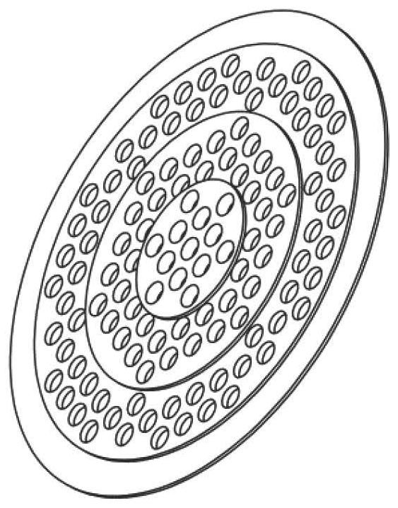
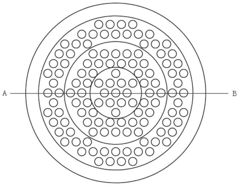
[0052] The invention provides a stepped grid suitable for ion thrusters, such as Figure 1-3 As shown, one side of the ladder gate is stepped, and the other side is flat;

[0053] The stepped grid is divided into a central area, a transition area and an edge area along the radial direction; multiple grid holes are set in the central area, transition area and edge area;

[0054] The thicknesses of the central region, the transition region and the edge region decrease sequentially, and the distances from the central region, the transition region and the edge region to another gate increase sequentially;

[0055] The ion current density in the central area is greater than the upper limit of the ion current density, the ion current density in the edge area is lower than the lower limit of the ion current density, and the ion current density in the transition area is between the ion current density in the central area and the edge area.

[0056] The central region has the largest ...

Embodiment 2

[0060] A grid structure of an ion thruster, such as Figure 5-7 As shown, the gate structure adopts the step gate provided by Embodiment 1 of the present invention, and the gate structure includes: a screen gate and an acceleration gate, at least one of the screen gate and the acceleration gate is a step gate.

[0061] Such as Figure 5 As shown, when the screen grid is a stepped grid and the accelerating grid is a planar grid, the ladder-shaped side of the screen grid faces the accelerating grid; the structure of the planar grid is as follows Figure 4 shown.

[0062] Such as Figure 6 As shown, when the screen grid is a planar grid and the acceleration grid is a stepped grid, the stepped side of the acceleration grid faces the screen grid; Loss of small beams of ions on the screen grid.

[0063] Such as Figure 7 As shown, when both the screen grid and the acceleration grid are stepped grids, the stepped side of the screen grid is opposite to the stepped side of the acc...

Embodiment 3

[0068] The present invention corresponds to the stepped grid of Embodiment 1 and the grid structure of Embodiment 2, and provides a method for determining the parameters of the stepped grid suitable for ion thrusters, such as Figure 8 As shown, the parameter determination methods include:

[0069] Step 101, determine the grid parameters at the center of the ion thruster through the thruster beam extraction experiment, as the grid parameters of the central area of ​​the stepped grid; grid parameters include grid spacing, grid thickness and grid hole diameter; grid The pole pitch is the distance between the central area of ​​the stepped gate and the two opposite faces of another gate in the gate structure; the gate thickness is the thickness of the central area of ​​the stepped gate;

[0070] Step 102, according to the grid parameters of the central area, determine the effective acceleration distance of the central area, specifically including:

[0071] According to the gate p...


PUM


Abstract

The invention relates to a step gate, a gate structure and a step gate parameter determination method and system. The gate is designed to be of a step-shaped structure; the step gate is divided into a central area, a transition area and an edge area in the radial direction; the thicknesses of the central area, the transition area and the edge area are sequentially reduced; the distances from the central area, the transition area and the edge area to the other gate are sequentially increased; the spacing of gates along the radial direction is changed; and the spacing of the gates in different areas is different, so that plasma sheaths at different radial positions have accelerating electric fields with proper intensity; and ion beams at different positions can be ensured to be well focused.

Description

technical field [0001] The invention relates to the technical field of miniature ion electric thrusters, in particular to a step grid, a grid structure, a method and a system for determining the parameters of the step grid. Background technique [0002] The ion thruster accelerates the ions in the discharge chamber plasma through the grid to generate thrust. The grid of the ion thruster generally includes a screen grid and an acceleration grid. The screen grid and the acceleration grid are generally porous structures. The screen grid holes and the acceleration grid The grid holes are aligned, and the plasma in the discharge chamber forms a spherical plasma sheath above the screen grid holes. Ions are emitted from the plasma sheath, accelerated by the electric field between the grids, and ejected from the acceleration grid holes to form an ion beam. The shape of the plasma sheath is related to the plasma parameters upstream of the screen grid. When the values ​​of the upstrea...

Claims


Application Information

Patent Timeline
IPC IPC(8): F03H1/00
CPCF03H1/0081
Inventor 杨鑫勇魏立秋韩亮王尚民李鸿丁永杰于达仁
Owner HARBIN INST OF TECH
Why Eureka
Try Eureka