Low-kinetic-energy pulsed ion source based on photoionization

A low kinetic energy, ion source technology, applied in the direction of ion beam tubes, circuits, discharge tubes, etc., can solve the problems of uncertainty in the interpretation of the reaction mechanism and the lack of quantum state selectivity of ions

Pending Publication Date: 2021-09-10
INST OF CHEM CHINESE ACAD OF SCI
View PDF9 Cites 0 Cited by
  • Summary
  • Abstract
  • Description
  • Claims
  • Application Information

AI Technical Summary

Problems solved by technology

The ion sources designed by Professor Wester and Professor Tian Shanxi's research group all use electron bombardment to generate reactant ions. The...

Method used


Image

  • Low-kinetic-energy pulsed ion source based on photoionization
  • Low-kinetic-energy pulsed ion source based on photoionization
  • Low-kinetic-energy pulsed ion source based on photoionization

Examples


Embodiment 1

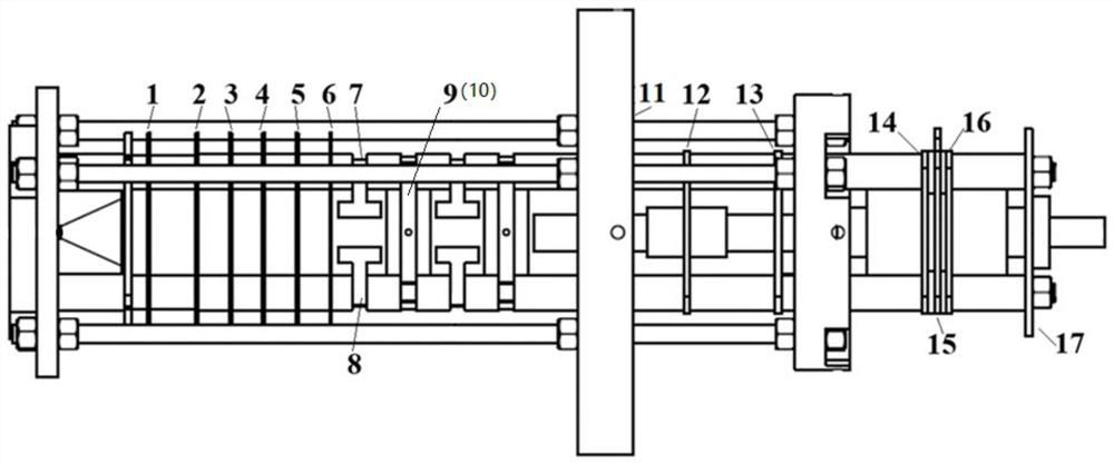
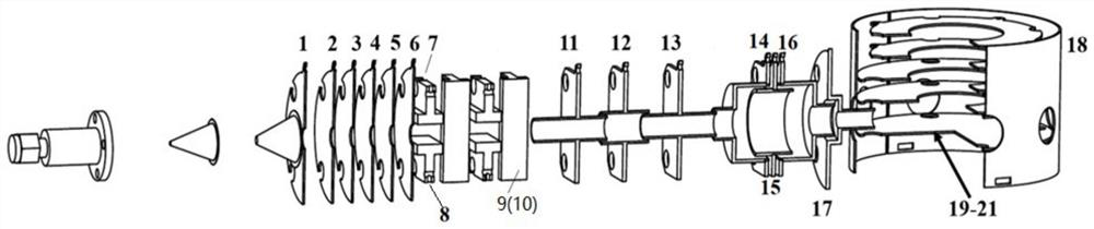
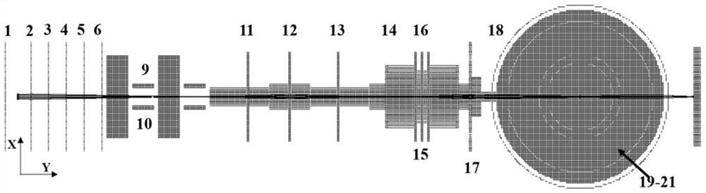
[0031] This embodiment discloses a low kinetic energy pulsed ion source based on photoionization, such as Figure 1-Figure 4 As shown, it includes: ion acceleration lens group, deflection electrode group, first focusing electrode group, second focusing electrode group and ion deceleration assembly.

[0032] The ion acceleration lens group is used to generate and accelerate ions, and initially focus the ion beam;

[0033] The deflection electrode group is used to correct the spatial position and velocity direction of the preliminarily focused ion beam;

[0034] The first focusing electrode group is used to refocus the corrected ion beam;

[0035] The second focusing electrode group is used to focus the ion beam for the third time, so that the focus of the ion beam falls on the center of the reaction zone;

[0036] The ion deceleration component is used to decelerate the ion beam after the third focus, and cooperate with the first focusing electrode group and the second focusi...

Embodiment 2

[0044] In order to check the overall performance of the ion source in the present invention, Ar is used as the test object in this embodiment, and Ar is prepared by means of (3+1) resonance-enhanced multi-photon ionization (REMPI) using a 314.5nm laser. + ion beam, the Ar + The ions are decelerated to different kinetic energies, and the best focusing state that can be achieved under different ion kinetic energies is explored. Such as Figure 5 , 6 as shown, Figure 5 , 6 They are the ion velocity imaging diagram and the corresponding translation energy spectrum when the kinetic energy of the ion beam is 1.64eV, respectively. It can be seen from the figure that the full width at half maximum of the kinetic energy of the ion beam is only 150meV at this time, and the focusing effect of the ion beam is equivalent to that of the ion source in the prior art. This shows that the scheme in the present invention can produce a pulsed ion beam that is continuously adjustable in the ...


PUM

PropertyMeasurementUnit
Outer diameteraaaaaaaaaa
The inside diameter ofaaaaaaaaaa
Outer diameteraaaaaaaaaa

Abstract

The invention belongs to the technical field of ion-molecule cross beam scattering, and relates to a low-kinetic-energy pulsed ion source based on photoionization. The low-kinetic-energy pulsed ion source comprises an ion acceleration lens group, a deflection electrode group, a first focusing electrode group, a second focusing electrode group and an ion deceleration assembly, wherein the ion acceleration lens group is used for generating and accelerating ions and primarily focusing ion beams, the deflection electrode group is used for correcting the spatial position and the speed direction of the preliminarily focused ion beam, the first focusing electrode group is used for carrying out secondary focusing on the corrected ion beam, the second focusing electrode group is used for carrying out third focusing on the ion beam so as to make the focus of the ion beam fall at the center of a reaction region, and the ion deceleration assembly is used for decelerating the ion beam focused for the third time, and is matched with the first focusing electrode group and the second focusing electrode group to optimize the focusing state of the ion beam. According to the invention, a multi-stage focusing mode is adopted to ensure that ions are kept in a good focusing state under the condition that kinetic energy is reduced to a very low degree.

Description

technical field [0001] The invention relates to a low kinetic energy pulsed ion source based on photoionization, which belongs to the technical field of ion-molecular cross beam scattering, in particular to the technical field of low kinetic energy pulsed ion source. Background technique [0002] Molecular reaction dynamics is a discipline that studies the molecular dynamic structure, reaction process, reaction rate and reaction mechanism in chemical reactions at the atomic and molecular levels. It involves both the internal motion of molecules and the collision between molecules. Understanding the micro-dynamic mechanism of a reaction system from the molecular level is the key to understanding the macro-dynamic behavior of the entire system. The collision reaction and energy transfer process between ions and molecules widely exist in complex gas-phase environments such as planetary atmospheres, interstellar space, plasma, and combustion processes. The study of collision dyn...

Claims


Application Information

Patent Timeline
IPC IPC(8): H01J27/24H01J27/02
CPCH01J27/24H01J27/02
Inventor 高蕻张国栋关力畅程敏
Owner INST OF CHEM CHINESE ACAD OF SCI
Why Eureka
Try Eureka