
Powder metallurgy finished product drying equipment

A technology of drying equipment and powder metallurgy, which is applied in drying, drying machines, lighting and heating equipment, etc., which can solve the problems of uncontrollable drying temperature and imperfect heat dissipation system, so as to reduce the temperature and prevent shock damage , the effect of preventing burns

Active Publication Date: 2021-11-05
烟台东星大韩粉末冶金有限公司
View PDF6 Cites 4 Cited by
  • Summary
  • Abstract
  • Description
  • Claims
  • Application Information

AI Technical Summary

Problems solved by technology

[0005] In order to overcome the shortcomings of uncontrollable drying temperature, imperfect heat dissipation system, and potential safety hazards, the technical problem to be solved is to provide a safe, effective, fast and energy-saving method that preserves high temperature during drying to improve drying efficiency and effect, After drying, the heat accumulated on the metallurgical products is released, and the temperature is lowered to prevent people from being scalded. Drying equipment for powder metallurgical products

Method used


Image

  • Powder metallurgy finished product drying equipment
  • Powder metallurgy finished product drying equipment
  • Powder metallurgy finished product drying equipment

Examples


Embodiment 1

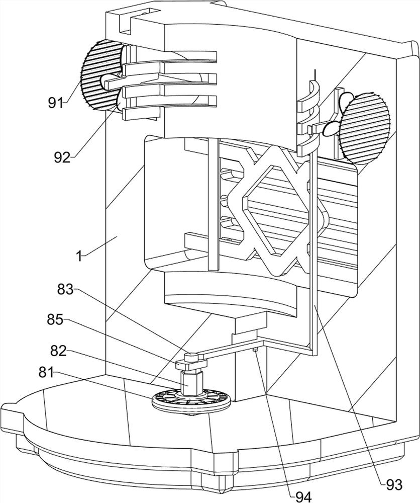
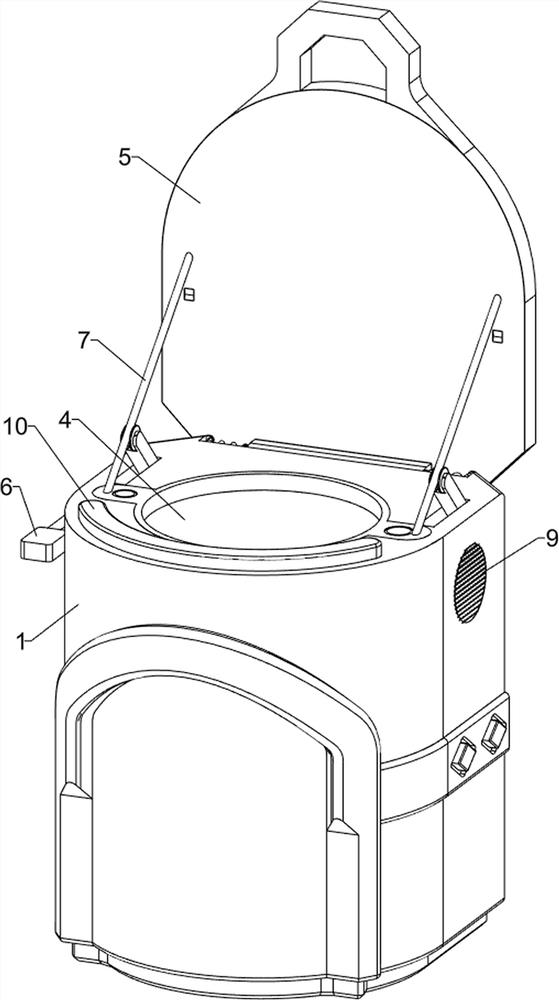
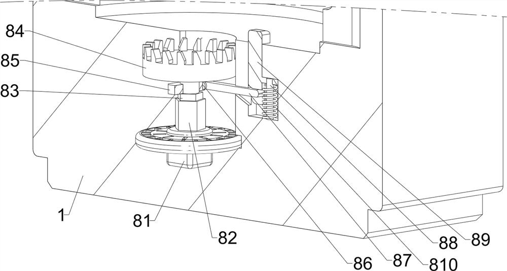
[0029] A drying equipment for powder metallurgy products, such as Figure 1-Figure 5 As shown, it includes a casing 1, a first fan blade 2, a heating pipe 3, a placement plate 4, a cover assembly 5 and a clamping assembly 6, and the rear side of the casing 1 is provided with the first fan blade 2 in a symmetrical rotation type, and the casing 1 There are vents on the left and right sides, a heating pipe 3 on the inner and rear side of the shell 1, a sliding plate 4 on the shell 1, a cover component 5 on the shell 1, and a clamping component 6 on the shell 1. The clamping component 6 cooperates with the cover component 5 .

[0030] First, people squeeze the clamping component 6 downward to unlock the clamping component 6 and the cover component 5, open the cover component 5, place the metallurgical products that need to be dried on the placement plate 4, and close the cover component 5 , the first fan blade 2 draws in the wind and converts the natural wind into hot air through...

Embodiment 2

[0036] On the basis of Example 1, such as Figure 6-Figure 9 As shown, it also includes a riser assembly 7, and the riser assembly 7 includes a second guide rod 71, a support plate 72, a second spring 73, a pull cord 74, a second connecting rod 75, a roller 76 and a spring 77, inside the housing 1 A second guide rod 71 is symmetrically arranged on the left and right, and a support plate 72 is slidably provided between the second guide rods 71. The placement plate 4 is connected to the support plate 72 in a rotational manner, and the support plate 72 is symmetrically connected to the shell 1 with a second guide rod. Two springs 73, the second spring 73 are respectively sleeved on the second guide rod 71, a stay rope 74 is symmetrically connected between the support plate 72 and the cover plate 52, and the left and right symmetrical rotation type is provided with the second connecting rod 75 on the shell 1, the second Both connecting rods 75 are provided with rollers 76 in a rotat...


PUM


Abstract

The invention relates to drying equipment, in particular to powder metallurgy finished product drying equipment. The technical problem is to provide the powder metallurgy finished product drying equipment which is safe, effective, rapid and energy-saving, can preserve high temperature during drying to improve the drying efficiency and effect, can dissipate heat accumulated on a metallurgy finished product after drying, can reduce the temperature and can prevent people from being scalded. According to the technical scheme, the powder metallurgy finished product drying equipment comprises a shell, first fan blades and a heating pipe. The first fan blades are symmetrically and rotationally arranged on one side in the shell; and the heating pipe is arranged on one side in the shell. According to the powder metallurgy finished product drying equipment, a clamping assembly is extruded downwards, so that the clamping assembly and a covering assembly are unlocked, the covering assembly is opened, metallurgy finished products needing to be dried are placed on a placing plate, the covering assembly is closed, air is sucked in through the first fan blades, natural air is converted into hot air through the heating pipe, and the metallurgy finished products are dried; and the safe, effective, rapid and energy-saving effects are achieved.

Description

technical field [0001] The invention relates to a drying equipment, in particular to a drying equipment for powder metallurgy products. Background technique [0002] The metallurgical finished product industry includes structural metallurgical finished product manufacturing, metal tool manufacturing, container and metal packaging container manufacturing, stainless steel and similar daily metallurgical finished product manufacturing, etc. With the progress of society and the development of science and technology, metallurgical manufacturing Products are used more and more widely in various fields of industry, agriculture and people's lives, and they also create more and more value for society. [0003] In actual use, the existing drying equipment for metallurgical products only uses heating tubes for drying, the drying efficiency is not high, and it is difficult to control the drying temperature. High, while the drying time of metallurgical products is shortened, because the...

Claims


Application Information

Patent Timeline
Patent Type & Authority Applications(China)
IPC IPC(8): F26B9/06F26B21/00F26B25/06
CPCF26B9/06F26B21/004F26B25/06
Inventor 陈槟
Owner 烟台东星大韩粉末冶金有限公司
Learn More