Hydrogen energy fuel cell with self-protection function

A fuel cell and hydrogen energy technology, applied in fuel cells, fuel cell additives, circuits, etc., can solve problems such as explosions, explosions at hydrogen refueling stations, and spontaneous combustion of hydrogen energy vehicles, and achieve the effect of reducing reactions

Active Publication Date: 2021-11-05
江西新节氢能源科技有限公司
View PDF0 Cites 0 Cited by
  • Summary
  • Abstract
  • Description
  • Claims
  • Application Information

AI Technical Summary

Problems solved by technology

[0002] Compared with pure electric vehicles, hydrogen energy batteries have obvious advantages and disadvantages. Hydrogen energy batteries last longer than lithium batteries and are more environmentally friendly, but compared to stability, lithium batteries are more stable than hydrogen energy batteries. The battery is stronger. In the process of hydrogen energy battery development, hydrogen energy vehicles will spontaneously ignite and hydrogen refueling stations will explode. However, for hydrogen storage tanks that can be used in vehicles, they are more stable and The protection of the hydrogen tank itself is good. When a hydrogen leak occurs, the hydrogen will be discharged to the outside in a very short time. However, there are hidden dangers in this method. When the hydrogen is discharged to the outside, it is easy to chemically react with the oxygen in the outside air, resulting in flames. , and hydrogen will explode when exposed to an open flame

Method used


Image

  • Hydrogen energy fuel cell with self-protection function
  • Hydrogen energy fuel cell with self-protection function
  • Hydrogen energy fuel cell with self-protection function

Examples


Embodiment Construction

[0023] The preferred embodiments of the present invention will be described in detail below in conjunction with the accompanying drawings, so that the advantages and features of the present invention can be more easily understood by those skilled in the art, so as to define the protection scope of the present invention more clearly.

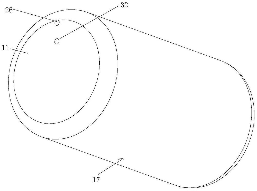
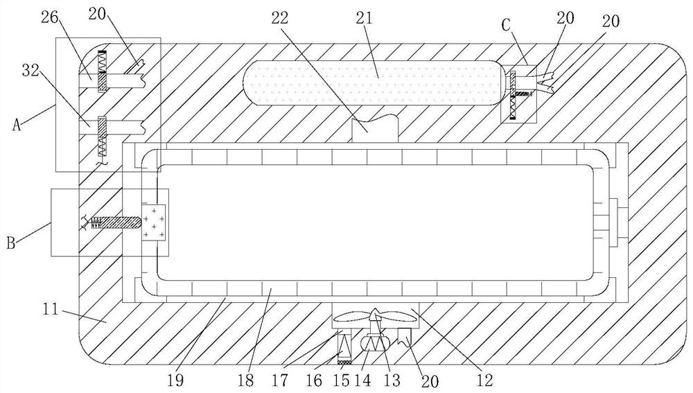
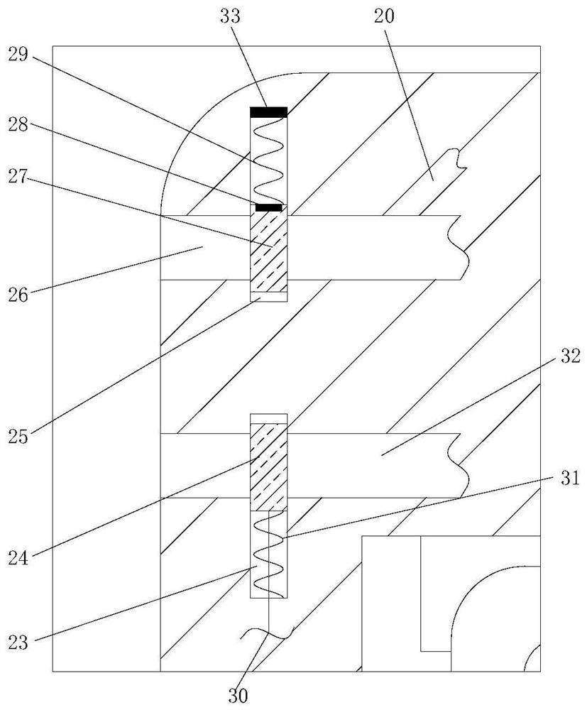
[0024] The structure of a hydrogen energy fuel cell with self-protection function in this embodiment is as follows: Figure 1 to Figure 6 Shown includes a housing 11, the housing 11 is provided with a storage chamber 19, a hydrogen storage tank 18 is stored in the storage chamber 19, and a temporary storage chamber 21 is provided in the housing 11 and located on the upper side of the storage chamber 19, the temporary storage chamber 21 The inside is filled with an inert gas such as helium, and the inner wall of one side of the storage cavity 19 is connected with a through cavity 12, and the through cavity 12 is provided with an air supply assembly...


PUM


Abstract

The invention discloses a hydrogen energy fuel cell with a self-protection function. The hydrogen energy fuel cell comprises a shell, a storage cavity is formed in the shell, a hydrogen storage tank is stored in the storage cavity, the inner wall of one side in the storage cavity is communicated with a through cavity, an air supply assembly is arranged in the through cavity, a fusible plug is placed at one end in the storage cavity, a detection assembly is arranged between the inner wall of the storage cavity and the fusible plug, a first cavity is formed in one end in the shell, a second cavity is formed in the position, located on the lower side of the first cavity, in the shell, a baffle assembly is arranged in the second cavity and can isolate the interior of the second cavity, a temporary storage cavity is formed in the position, located on the upper side of the storage cavity, in the shell, and the temporary storage cavity is filled with inert gas. The hydrogen storage tank is primarily protected by adding inert gas around the hydrogen storage tank, the hydrogen storage tank is prevented from reacting with oxygen, a large amount of inert gas is mixed into the hydrogen while the hydrogen is rapidly released to the outside, the dilution effect is achieved, and therefore when the hydrogen is discharged to the outside, the reaction of the hydrogen with the oxygen in the air can be reduced.

Description

technical field [0001] The invention relates to the technical field of hydrogen energy cells, in particular to a hydrogen energy fuel cell with self-protection function. Background technique [0002] Compared with pure electric vehicles, hydrogen energy batteries have obvious advantages and disadvantages. Hydrogen energy batteries last longer than lithium batteries and are more environmentally friendly, but compared to stability, lithium batteries are more stable than hydrogen energy batteries. The battery is stronger. In the process of hydrogen energy battery development, hydrogen energy vehicles will spontaneously ignite and hydrogen refueling stations will explode. However, for hydrogen storage tanks that can be used in vehicles, they are more stable and The protection of the hydrogen tank itself is good. When a hydrogen leak occurs, the hydrogen will be discharged to the outside in a very short time. However, there are hidden dangers in this method. When the hydrogen is ...

Claims


Application Information

Patent Timeline
IPC IPC(8): H01M8/04082H01M8/04089H01M8/22
CPCH01M8/04201H01M8/04089H01M8/22Y02E60/50
Inventor 宋梓煜王琼
Owner 江西新节氢能源科技有限公司
Why Eureka
Try Eureka