Novel steam-water separation device

A technology of steam-water separation device and separation device, which is applied in the direction of combination device, separation method, and dispersed particle separation, etc. It can solve the problems that internal parts are easily corroded by water vapor, reduce the service life of the device, increase the difficulty of maintenance, etc., and achieve good results. Sealing, reducing rust, reducing the effect of scattering

Active Publication Date: 2021-11-09
山东豪迈重型装备有限公司
View PDF4 Cites 1 Cited by
  • Summary
  • Abstract
  • Description
  • Claims
  • Application Information

AI Technical Summary

Problems solved by technology

[0006] Aiming at the deficiencies of the prior art, the present invention provides a new type of steam-water separation device, which solves the problem of insufficient collection, the device is not easy to be controlled, and the internal components are easily corroded by water vapor, which reduces the service life of the device, and the device The problem of increasing the difficulty of repair after damage

Method used


Image

  • Novel steam-water separation device
  • Novel steam-water separation device
  • Novel steam-water separation device

Examples


Embodiment 1

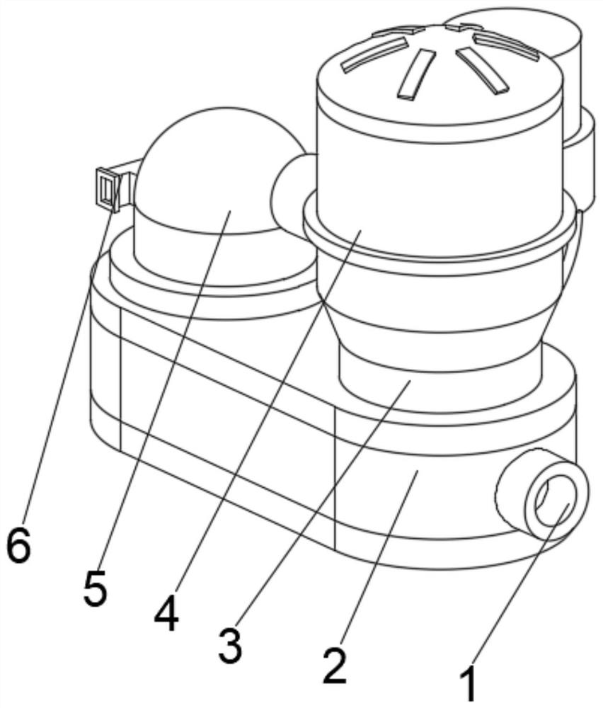
[0040] see Figure 1-6 , the present invention provides a technical solution: a new type of steam-water separation device, including a water storage base 2, the middle part of the outer wall on the right side of the water storage base 2 is connected with an air outlet pipe 1, and the top left side of the water storage base 2 is connected with a drain tube 5 , the middle part of the left outer wall of the hydrophobic cylinder 5 is connected with an air intake pipe 6, the top right middle part of the water storage base 2 is fixedly connected with a fastening plate 3, the top of the fastening plate 3 is provided with a separation device 4, and the bottom of the separation device 4 runs through The fastening plate 3 extends to the inside of the fastening plate 3 .

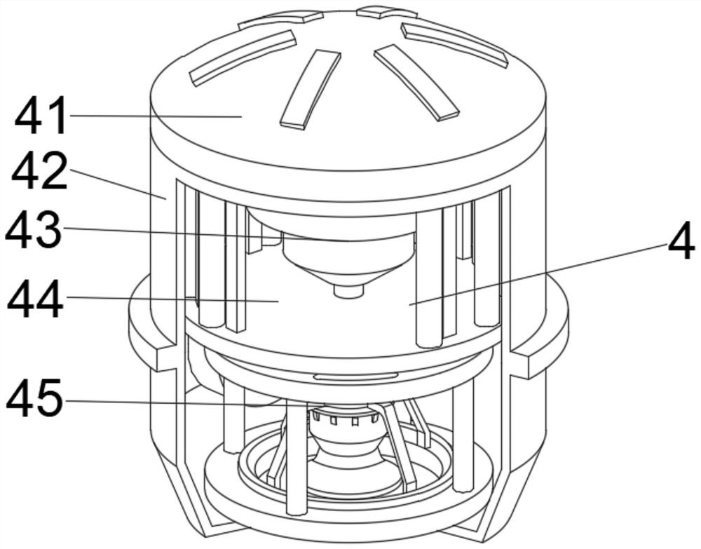
[0041] Wherein, the separation device 4 includes a separation tank 42, the top of the separation tank 42 is provided with a sealing top cover 41, the middle position of the inner cavity bottom of the separation tank 42...

Embodiment 2

[0047] see Figure 1-6 , on the basis of Embodiment 1, the present invention provides a technical solution: a method of using a new type of steam-water separation device, step 1: install the device, and insert the hydrophobic cylinder 5 into the water storage base 2, use the tight The clamping connection of the fixing plate 3 connects the separation device 4 with the water storage base, and fills the inside of the water storage base 2 with water;

[0048] Step 2: Connect the separation tank 42 with the external circulation pipeline, connect the solid bracket 44 with the separation mechanism 43, and communicate with the flow guide mechanism 45 through the separation mechanism 43 through the communication pipe to realize internal quantitative transfer;

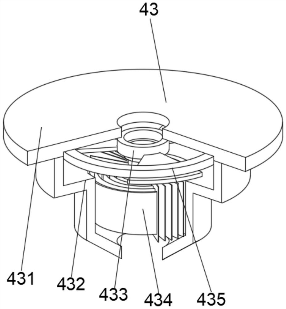
[0049] Step 3: Connect the multiple separation body 434 to the power part through the rotating frame 433, and use the limit ring 435 to support the rotating frame 433, so as to achieve the flow chamber where the internal rotatio...


PUM


Abstract

A disclosed novel steam-water separation device comprises a water storage base, an air outlet pipe communicates with the middle of the outer wall of the right side of the water storage base, a drainage cylinder communicates with the left side of the top of the water storage base, an air inlet pipe communicates with the middle of the outer wall of the left side of the drainage cylinder, a fastening plate is fixedly connected to the middle of the right side of the top of the water storage base, and the top of the fastening plate is provided with a separation device. The invention relates to the technical field of steam power. According to the novel steam-water separation device, the situation of leakage in the water flow conveying process is avoided, internal parts are convenient to maintain after being damaged through opening and closing of the sealing top cover, in the communicating process of the middle fixing support, steam is convenient to transfer, internal parts are protected, corrosion to the parts is reduced, and the separation mechanism is connected with a flow guide mechanism, so that it is guaranteed that internal water flow can be fully collected, the interior has good sealing performance, and the situation that the interior is in a completely wet state is avoided.

Description

technical field [0001] The invention relates to the technical field of steam power, in particular to a novel steam-water separation device. Background technique [0002] The steam-water separator is carbon steel or stainless steel equipment with a pressure vessel structure. The steam-water separator must be installed on a horizontal pipeline with the drain outlet vertically downward. If the liquid is discharged quickly, a suitable set of steam traps should be connected to the drain at the bottom of the steam-water separator. Generally, this type of valve should be installed horizontally in the pipeline. [0003] According to a rotary vane type steam-water separator disclosed in Chinese Patent No. CN112221254A, the steam-water mixture inlet connecting pipe under the rotating vane separator is horizontally arranged, and an elbow is used to connect the rotating vane separator and the steam-water mixture inlet connecting pipe, so as to reduce the number of rotating blades. The ...

Claims


Application Information

Patent Timeline
Patent Type & Authority Applications(China)
IPC IPC(8): B01D50/00
Inventor 齐霁
Owner 山东豪迈重型装备有限公司
Why Eureka
Try Eureka