Automatic welding device for steel structure shell
An automatic welding and steel structure technology, applied in the direction of auxiliary devices, welding equipment, auxiliary welding equipment, etc., can solve the problems that the welding torch cannot move accurately and lock the welding angle, etc., and achieve the effect of improving precision and stability and avoiding displacement
- Summary
- Abstract
- Description
- Claims
- Application Information
AI Technical Summary
Problems solved by technology
Method used
Image

Examples
Embodiment Construction
[0054] The present invention is described in further detail now in conjunction with accompanying drawing. These drawings are all simplified schematic diagrams, which only illustrate the basic structure of the present invention in a schematic manner, so they only show the configurations related to the present invention.
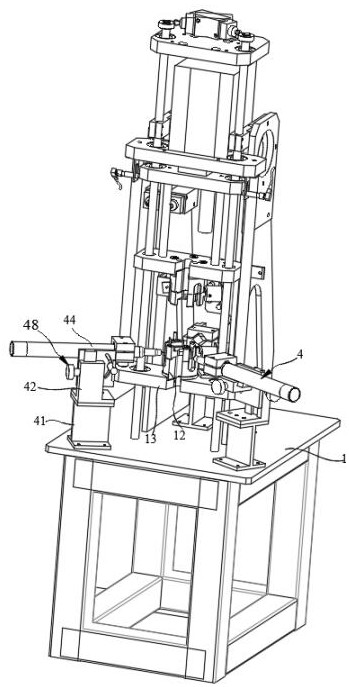
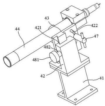
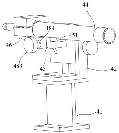
[0055] Such as Figures 1 to 11 As shown, an automatic welding device for a steel structure shell of the present invention includes: a workbench 1, a fixed platform 13 and two welding parts 4, wherein the workbench 1 is suitable for supporting the above-mentioned components; the fixed platform 13 is arranged on the workbench 1 In the middle of the end face; the welding part 4 is arranged on both sides of the fixed platform 13 . For each of the above components, a detailed description will be given below.
[0056] workbench
[0057] The workbench 11 is arranged on a horizontal work surface, and the upper end surface of the workbench 11 is flat and parallel t...
PUM
 Abstract
Description
Claims
Application Information