Working method of vacuum pump system in vacuum coating and vacuum pump system

A technology of vacuum coating and working method, which is applied in vacuum evaporation coating, sputtering coating, ion implantation coating, etc., to achieve the effect of cost saving and simple operation

Inactive Publication Date: 2021-11-09
BETONE TECH SUZHOU INC
View PDF5 Cites 0 Cited by
  • Summary
  • Abstract
  • Description
  • Claims
  • Application Information

AI Technical Summary

Problems solved by technology

[0005] For this reason, the technical problem to be solved by the present invention is to overcome the defects of the continuous use of protective gas in the prior art, and provide a working method and vacuum pump system of the vacuum pump system in vacuum coating, so as to realize timely feeding suitable gas into the vacuum pump, so as to On the premise of ensuring the reliability of the equipment, the cost of using shielding gas is reduced

Method used


Image

  • Working method of vacuum pump system in vacuum coating and vacuum pump system
  • Working method of vacuum pump system in vacuum coating and vacuum pump system
  • Working method of vacuum pump system in vacuum coating and vacuum pump system

Examples


Embodiment Construction

[0030] The present invention will be further described below in conjunction with the accompanying drawings and specific embodiments, so that those skilled in the art can better understand the present invention and implement it, but the examples given are not intended to limit the present invention.

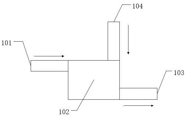
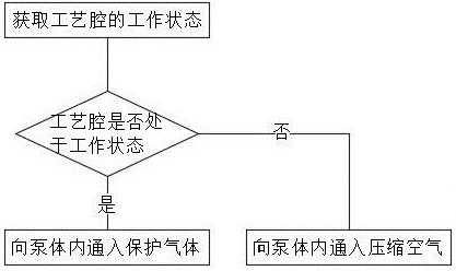
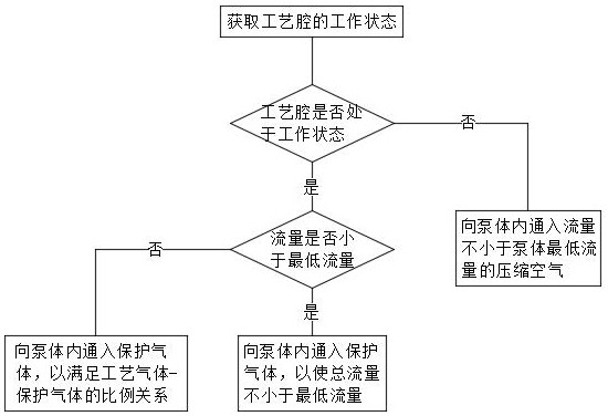
[0031] refer to figure 2 Shown is a flow chart of the working method of the vacuum pump system in a vacuum coating of the present invention. In the working method of the present invention, the vacuum pump system includes a process chamber, a pump body 202, a protective gas source and a compressed air source, including the following steps:

[0032] S10: Obtain the working state of the process chamber. When the process chamber is in the working state, execute S20. When the process chamber is in the non-working state, execute S30. When the process chamber is working, process gas enters the pump body 202. In order to prevent the process gas from When the pump body 202 is damaged, th...


PUM


Abstract

The invention relates to a working method of a vacuum pump system in vacuum coating and the vacuum pump system. The vacuum pump system comprises a process cavity, a pump body, a protective gas source and a compressed air source; the working method comprises the following steps that S10, the working state of the process cavity is obtained; when the process cavity is in the working state, S20 is executed; when the process cavity is in the non-working state, S30 is executed; S20, the protective gas source and the pump body are communicated, and protective gas enters the pump body; and S30, the compressed air source communicates with the pump body, and compressed air enters the pump body. By judging the working state of the process cavity, proper gas is introduced into a vacuum pump in good time, and the cost is reduced.

Description

technical field [0001] The invention relates to the technical field of vacuum coating, in particular to a working method of a vacuum pump system in vacuum coating and the vacuum pump system. Background technique [0002] In semiconductor vacuum equipment, especially chemical vapor deposition equipment, the process chamber should be kept in a vacuum state at all times. During the coating process, the unreacted gas will be pumped into the waste gas treatment machine by the vacuum pump for treatment. During the entire chemical vapor deposition process, the total gas utilization rate is less than 10%, and a large amount of unreacted gas is discharged. When the exhaust gas is discharged to the outlet of the vacuum pump, the pressure will rise to 600 Pa, and the temperature will drop to about 100 degrees. 2 The concentration rises rapidly. At this time, the components in the exhaust gas are SiH 4 、H 2 , N 2 and NH 3 Etc., the gas in the exhaust gas reacts with each other or...

Claims


Application Information

Patent Timeline
Patent Type & Authority Applications(China)
IPC IPC(8): C23C14/56C23C14/54
Inventor 刘祥宋维聪封拥军郑倪明罗傢蛴崔世甲
Owner BETONE TECH SUZHOU INC
Why Eureka
Try Eureka