Lifting device and method for liftable in-well equipment in in-situ leaching uranium mining mine

An in-situ leaching uranium mining and lifting well technology, which is applied in the direction of lifting devices, lifting frames, earthwork drilling and mining, etc., can solve the problems of equipment lifting in the well, poor passability, and high center of gravity of the lifting device, so as to increase the height of equipment and reduce the required Time, reduce the effect of labor intensity

Pending Publication Date: 2021-11-09
中核通辽铀业有限责任公司
View PDF7 Cites 0 Cited by
  • Summary
  • Abstract
  • Description
  • Claims
  • Application Information

AI Technical Summary

Problems solved by technology

It solves the problem of poor passability caused by the high center of gravity of the hoisting device in the well and the inability to lift the equipment in the well in complex terrain, improves the hoisting efficiency of the equipment in the well, and reduces the labor intensity of personnel

Method used


Image

  • Lifting device and method for liftable in-well equipment in in-situ leaching uranium mining mine
  • Lifting device and method for liftable in-well equipment in in-situ leaching uranium mining mine

Examples


Embodiment Construction

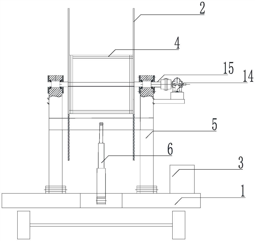
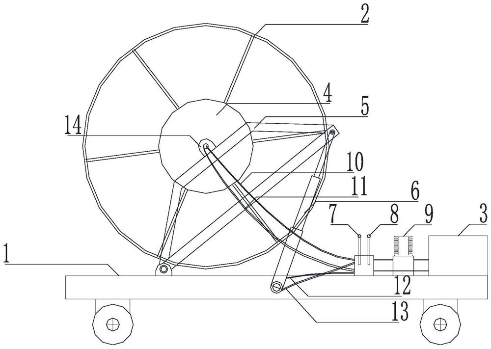
[0034] A hoisting device for hoisting equipment in an in-situ leaching uranium mining mine, which includes a vehicle frame 1, a power unit, a hoisting device and a coiling device.

[0035] The power unit includes a hydraulic pump 9, a rotary controller 8, a high-pressure oil pipe group, a hydraulic motor 14 and a transmission shaft 15: wherein the high-pressure oil pipe group includes a hydraulic oil pipe A10, a hydraulic oil pipe B11, a hydraulic oil pipe C12, and a hydraulic oil pipe D13; the rotation control The upper inlet port of the device 8 is connected to the output port of the hydraulic pump 9, the upper outlet port of the rotary controller 8 is connected to the inlet port of the hydraulic motor 14, the lower inlet port of the rotary controller 8 is connected to the outlet port of the hydraulic motor 14, and the rotary controller 8 The lower outlet port of the hydraulic pump 9 is connected to the inlet port of the hydraulic oil tank 3, and the inlet port of the hydraul...


PUM


Abstract

The invention provides a lifting device and method for liftable in-well equipment in an in-situ leaching uranium mining mine. The lifting device comprises a frame, a power device, a lifting device and a pipe coiling device. The lifting device ascends and descends through a hydraulic device, and meanwhile power is provided for a winch. The problems that due to the fact that the gravity center of an in-well equipment lifting device is too high, trafficability is poor, and in-well equipment lifting operation cannot be conducted on complex terrains are solved, the in-well equipment lifting efficiency is improved, and the labor intensity of workers is reduced.

Description

technical field [0001] The invention belongs to the field of in-situ leaching uranium mining well site process drilling equipment maintenance field, and in particular relates to an in-situ leaching uranium mine lifting device and method for lifting equipment in the well. Background technique [0002] Well equipment lifting technology is CO 2 +O 2 One of the core technologies of the in-situ leaching uranium mining engineering wellsite process is to lift the well pipe, well cable and multi-stage submersible pump through the well equipment lifting device. After the repair by the maintenance personnel, the pipe in the pumping well, the cable in the well and the multi-stage submersible pump are lowered into the borehole through the hoisting device of the equipment in the well. The uranium-containing solution is collected into the centralized control room through submersible pumps, well pipes, and surface pipes. [0003] In the process of production and operation, submersible p...

Claims


Application Information

Patent Timeline
Patent Type & Authority Applications(China)
IPC IPC(8): E21B23/04B66F7/18B66F7/20
CPCE21B23/04B66F7/18B66F7/20
Inventor 赵生祥原渊张勇阮志龙张万亮李喜龙曹俊鹏贺刚闫纪帆杨少武林垚王丽坤
Owner 中核通辽铀业有限责任公司
Why Eureka
Try Eureka