Eureka AIR delivers breakthrough ideas for toughest innovation challenges, trusted by R&D personnel around the world.

Direct connection type screw air compressor oil-gas separation assembly,

A technology for separating components and oil and gas separation tanks, which is applied in the direction of rotary piston type/swing piston type pump components, pump components, mechanical equipment, etc. Airtightness, easy replacement, and the effect of reducing energy consumption

Inactive Publication Date: 2021-11-09
山东众海机械有限公司
View PDF0 Cites 0 Cited by
  • Summary
  • Abstract
  • Description
  • Claims
  • Application Information

AI Technical Summary

Problems solved by technology

[0004] 1. When the existing direct-coupled screw air compressor oil-gas separation assembly is in use, because the separation assembly itself does not have the anti-leakage function, once the asbestos pad between the oil separation core flange and the tank flange is damaged, it will Will lead to gas leakage, which will increase the cost
[0005] 2. When the existing direct-coupled screw air compressor oil-gas separation assembly is in use, because the separation assembly itself does not have the function of easy disassembly, once the oil separation core is damaged, it will lead to an increase in replacement time and reduce the device. work efficiency
[0006] 3. When the existing direct-coupled screw air compressor oil-gas separation assembly is in use, because the separation assembly itself does not have the function of diversion, once the compressed air flows irregularly after entering the separation tank, it will cause energy loss , thereby reducing the practicality of the device

Method used


Image

  • Direct connection type screw air compressor oil-gas separation assembly,
  • Direct connection type screw air compressor oil-gas separation assembly,
  • Direct connection type screw air compressor oil-gas separation assembly,

Examples


Embodiment Construction

[0029] The following will clearly and completely describe the technical solutions in the embodiments of the present invention with reference to the accompanying drawings in the embodiments of the present invention. Obviously, the described embodiments are only some, not all, embodiments of the present invention. Based on the embodiments of the present invention, all other embodiments obtained by persons of ordinary skill in the art without making creative efforts belong to the protection scope of the present invention.

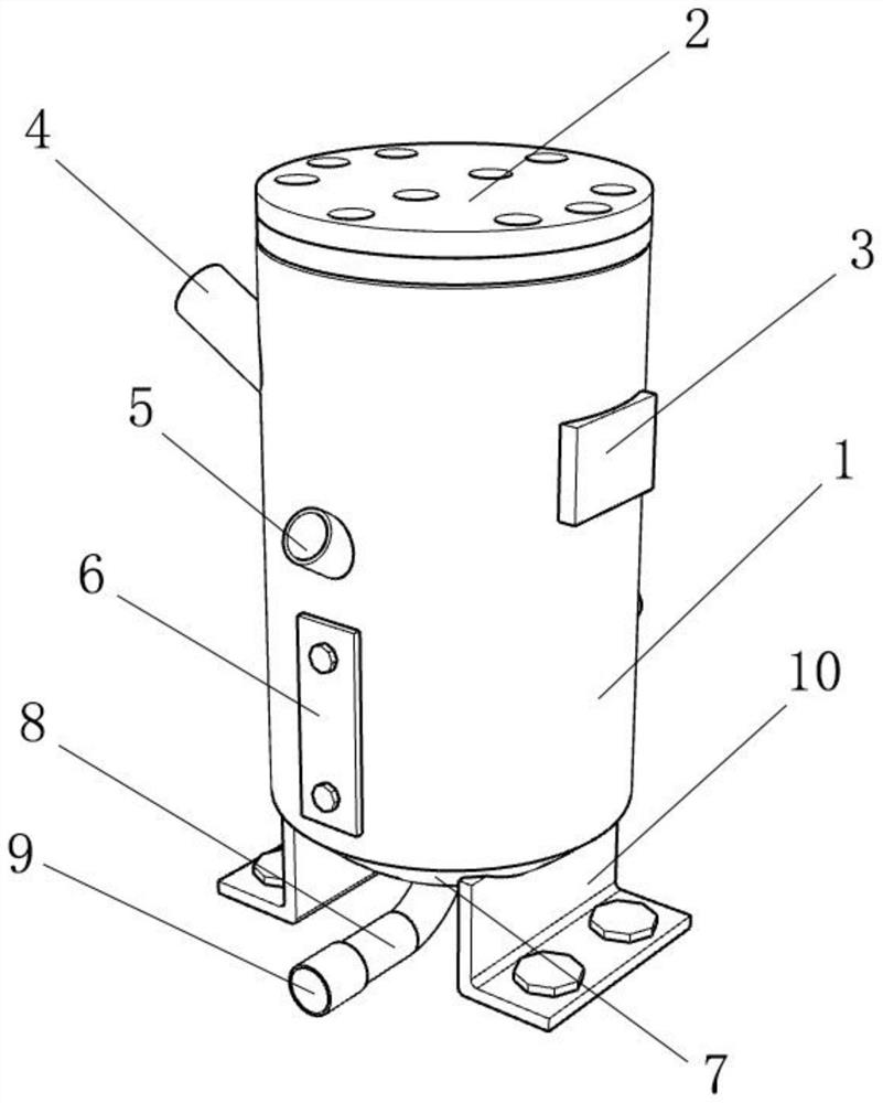
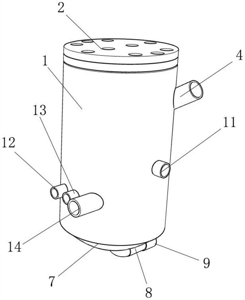
[0030] as attached figure 1 with attached Figure 6 The shown direct-coupled screw air compressor oil-gas separation assembly includes an oil-gas separation tank body 1, an oil-gas barrel flange 2 is detachably installed on the top of the oil-gas separation tank body 1, and the top of one side of the oil-gas separation tank body 1 The nameplate seat 3 is detachably installed, the top of the other side of the oil-gas separation tank body 1 is welded with a ref...


PUM


Abstract

The invention discloses a direct connection type screw air compressor oil-gas separation assembly, and particularly relates to the field of screw air compressors, the direct connection type screw air compressor oil-gas separation assembly comprises an oil-gas separation tank body, wherein an oil-gas barrel flange plate is detachably installed at the top end of the oil-gas separation tank body, and a name plate seat is detachably installed at the top end of one side of the oil-gas separation tank body; an oil filling hole is welded to the top end of the other side of the oil-gas separation tank body, an air inlet is welded to the middle of the front face of the oil-gas separation tank body, an oil immersion lens fixing plate is detachably installed at the bottom end of the front face of the oil-gas separation tank body, the surface of the bottom end of the oil-gas separation tank body is communicated with an oil-gas barrel plug, and the bottom end of the oil-gas barrel plug is communicated with a drain outlet. According to the direct connection type screw air compressor oil-gas separation assembly, the oil filling hole, a flange base, a sealing ring and an oil separation core are matched with one another, so that the sealing performance of the device is guaranteed, and the problem that the cost is increased due to the fact that gas leakage is caused once an asbestos pad between an oil separation core flange and a tank body flange is damaged due to the fact that a separation assembly does not have a leakage-proof function is solved.

Description

technical field [0001] The invention relates to the technical field of screw air compressors, more specifically, the invention relates to an oil-gas separation assembly of a direct-coupled screw air compressor. Background technique [0002] The screw air compressor is mainly composed of the main body of the air compressor, motor, air storage tank, oil storage tank, oil cooler and oil-gas separation tank. The main function of the oil-gas separation tank is to store lubricating oil and separate oil and gas. After being separated by the oil-gas separation tank, the residual amount of lubricating oil in the compressed air can be reduced, thereby reducing the lubricating oil consumption of the air compressor. Generally, it is installed on the bottom plate together with the motor, air storage tank, oil storage tank and oil cooler; The oil and gas separation tank will compress the air to flow irregularly in the tank. After entering the oil separation core to filter the lubricating ...

Claims


Application Information

Patent Timeline
Patent Type & Authority Applications(China)
IPC IPC(8): F04C29/02
CPCF04C29/026
Inventor 刘春海
Owner 山东众海机械有限公司
Why Eureka
Eureka Blog
Learn More