Intelligent radar liquid level meter

A radar level gauge, intelligent technology, applied in the field of measuring instruments, can solve problems such as cumbersome operation, affecting the measurement accuracy of radar level gauge, inconvenient disassembly, etc., to achieve the effect of ensuring measurement accuracy

Inactive Publication Date: 2021-11-09
许华杰
View PDF0 Cites 0 Cited by
  • Summary
  • Abstract
  • Description
  • Claims
  • Application Information

AI Technical Summary

Problems solved by technology

[0003] Most of the existing radar level gauges are fixed by flanges, and they need to be locked with multiple screws when fixing them. It is cumbersome and inconvenient to disassemble, which will reduce the efficiency of maintenance or replacement parts, and when measuring some liquids, due to its own nature, there will be foam on the surface, and the existence of foam will affect the measurement accuracy of the radar level gauge problem, the present invention provides an intelligent radar liquid level gauge to solve the above problems

Method used


Image

  • Intelligent radar liquid level meter
  • Intelligent radar liquid level meter
  • Intelligent radar liquid level meter

Examples


Embodiment 1

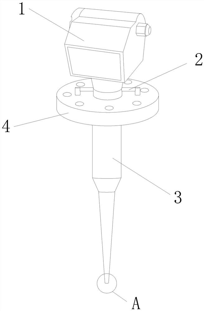
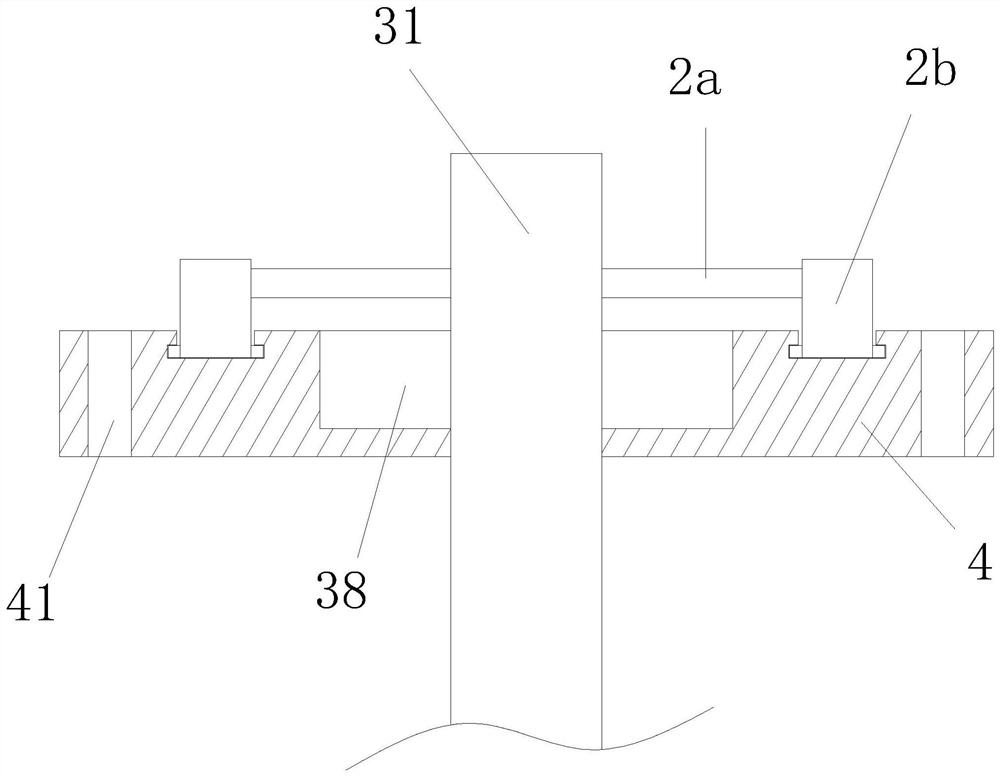
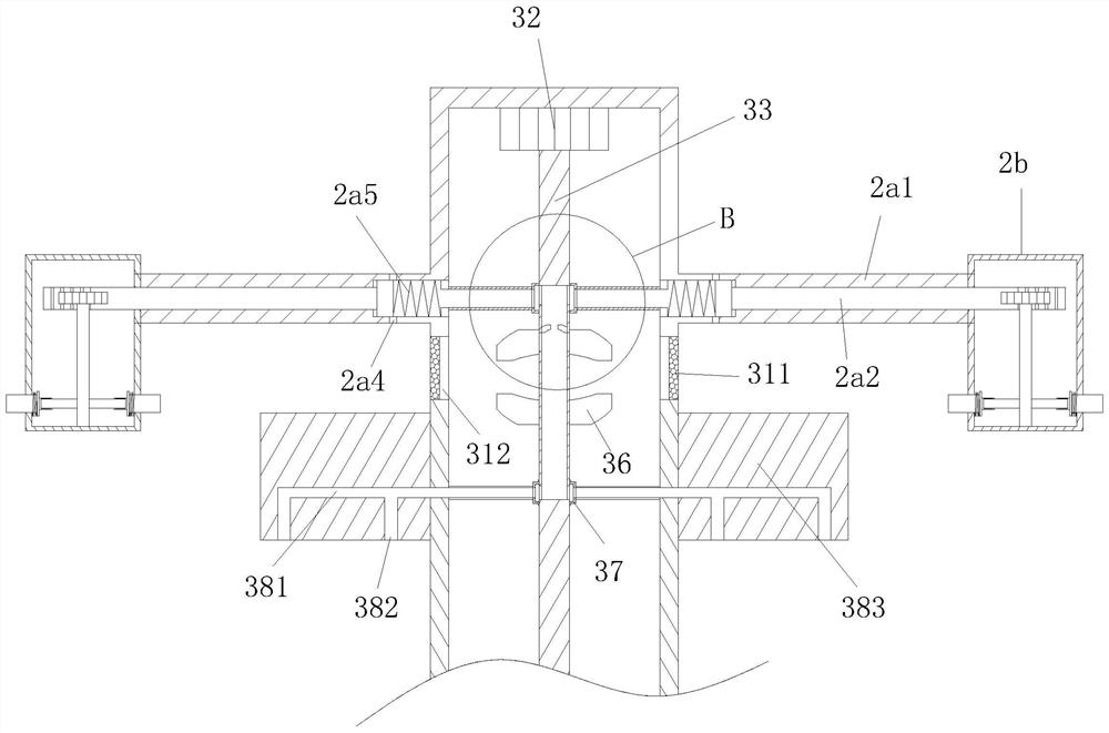
[0028] see Figure 1-4 , the present invention provides an intelligent radar liquid level gauge, the structure of which includes a main body 1, a fixing device 2, a probe 3, and a mounting flange 4, the bottom of the main body 1 is fixed on the top of the probe 3, and the outer surface of the probe 3 is A fixing device 2 is installed on the upper body, the fixing device 2 is located under the main body 1, the fixing device 2 is matched with the mounting flange 4, the mounting flange 4 is located under the fixing device 2 and connected with the probe 3, the probe 3 includes a rod body 31. Micromotor 32, main shaft 33, No. 1 connection ring 34, upflow fan 35, downflow fan 36, No. 2 connection ring 37, adsorption mechanism 38, air jet 39, micromotor 32 and micromotor 32 are installed on the inner top of rod body 31 The output shaft is connected with the top of the main shaft 33, and the outer surface of the main shaft 33 is movably connected with a No. 1 connecting ring 34 and a ...

Embodiment 2

[0037] see Figure 1-4 , the present invention provides an intelligent radar liquid level gauge, the structure of which includes a main body 1, a fixing device 2, a probe 3, and a mounting flange 4, the bottom of the main body 1 is fixed on the top of the probe 3, and the outer surface of the probe 3 is A fixing device 2 is installed on the upper body, the fixing device 2 is located under the main body 1, the fixing device 2 is matched with the mounting flange 4, the mounting flange 4 is located under the fixing device 2 and connected with the probe 3, the probe 3 includes a rod body 31. Micromotor 32, main shaft 33, No. 1 connection ring 34, upflow fan 35, downflow fan 36, No. 2 connection ring 37, adsorption mechanism 38, air jet 39, micromotor 32 and micromotor 32 are installed on the inner top of rod body 31 The output shaft is connected with the top of the main shaft 33, and the outer surface of the main shaft 33 is movably connected with a No. 1 connecting ring 34 and a ...


PUM


Abstract

The invention discloses an intelligent radar liquid level meter which structurally comprises a main body, a fixing device, a wave guide rod and a mounting flange. The main body bottom is fixed on the top of the wave guide rod; a fixing device is mounted on the outer side surface of the wave guide rod; the fixing device is positioned below the main body; the fixing device is matched with the mounting flange; and the mounting flange is positioned below the fixing device and is connected with the wave guide rod. The device has the advantages that the clamping block is clamped with the mounting flange, negative pressure is generated by the adsorption opening through air exhaust to obtain suction force to be adsorbed on the mounting flange, the mounting and fixing effect is guaranteed; besides, the purpose of quick dismounting can be achieved by controlling the micromotor; meanwhile, air flow generated by the downward flow fan can blow away foam on the liquid level of a measurement point after being sprayed out through the air spraying opening, so that the measurement precision is guarantee and the problems that an existing radar liquid level meter is inconvenient to disassemble integrally and the measurement precision is affected by the foam on the liquid surface during measurement are solved.

Description

technical field [0001] The invention relates to the field of measuring instruments, in particular to an intelligent radar liquid level gauge. Background technique [0002] The radar level gauge is a general-purpose radar level gauge. It is a measuring instrument based on the principle of time travel. The radar wave runs at the speed of light, and the running time can be converted into a level signal through electronic components. It is an instrument that sends out a high-frequency pulse from the probe and propagates in space at the speed of light. When the pulse encounters the surface of the material, it is reflected back and received by the receiver in the instrument, and the distance signal is converted into a material level signal. The existing radar liquid level Most of the gauges are fixed by flanges, and they need to be locked with multiple screws when fixing them. In the case of maintenance or replacement of parts, if the overall disassembly is performed, the operatio...

Claims


Application Information

Patent Timeline
Patent Type & Authority Applications(China)
IPC IPC(8): G01F23/284
CPCG01F23/284
Inventor 许华杰
Owner 许华杰
Why Eureka
Try Eureka