Asymmetry calibration method for overlay error measurement

An overlay error and symmetry technology, applied in the field of photolithography, can solve problems affecting measurement accuracy and changes in the intensity distribution of diffracted light

Pending Publication Date: 2022-07-01
SHANGHAI MICRO ELECTRONICS EQUIP (GRP) CO LTD
View PDF1 Cites 1 Cited by
  • Summary
  • Abstract
  • Description
  • Claims
  • Application Information

AI Technical Summary

Problems solved by technology

[0006] The purpose of the present invention is to provide a device and method for overlay error measurement, which can solve the problem that the light intensity distribution of diffracted light changes due to changes in the position of overlay marks, thereby affecting the measurement accuracy

Method used


Image

  • Asymmetry calibration method for overlay error measurement
  • Asymmetry calibration method for overlay error measurement
  • Asymmetry calibration method for overlay error measurement

Examples


Embodiment 1

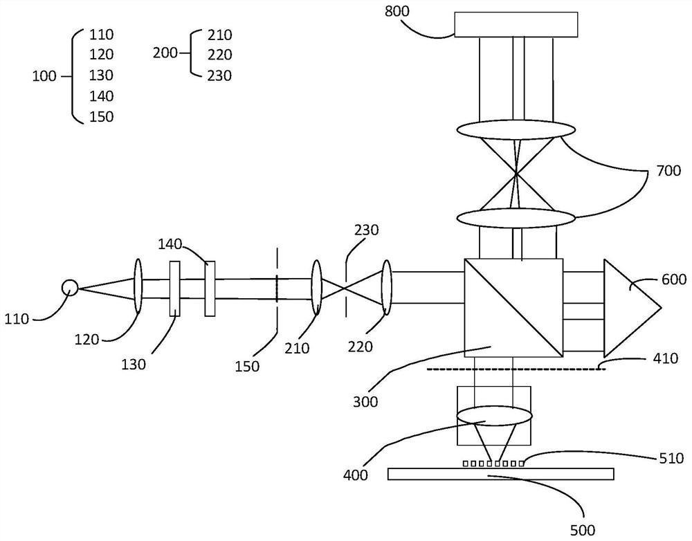
[0051] figure 1 This is a schematic structural diagram of a device for measuring overlay error in this embodiment. like figure 1 As shown, the device for measuring the overlay error includes:

[0052] The light source module 100 is used to provide a measurement spot. The light source module 100 is sequentially provided with: a light source 110 , a collimating lens 120 , a narrow-band filter 130 , a polarizer 140 and an aperture stop 150 along the optical path.

[0053] The light source 110 may be a white light source 110 , a broadband light source 110 or a composite light source 110 composed of several discrete spectral lines. The light source 110 may be a surface light source 110, a line light source 110 or a point light source 110, and a light source 110 with other spot shapes, and the measurement spot generated by the light source module 100 is several of ultraviolet light, visible light, and infrared light. Preferably, the measurement spot is light of a single waveleng...

Embodiment 2

[0115] In the method for asymmetry calibration of overlay error measurement provided in this embodiment, the same parts as those in Embodiment 1 will not be described here, and only different points will be described below.

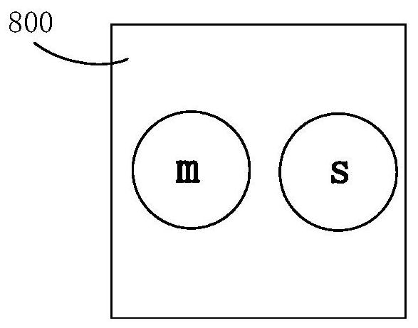
[0116] The difference between this embodiment and the first embodiment is that the step of acquiring the light intensity of the diffracted light by the detector 800 and generating the first reference signal further includes:

[0117] When the detector 800 acquires the diffracted light, the overlay mark 510 moves in multiple steps along the direction of the horizontal component of the measurement spot, and after each step movement, the detector 800 acquires the The light intensity of the diffracted light of the mark 510 is overwritten to generate a first measurement signal, and the average value of the first measurement signals is taken as the first reference signal.

[0118] The step of acquiring the light intensity of the diffracted light by the detector...

Embodiment 3

[0126] In the method for asymmetry calibration of overlay error measurement provided in this embodiment, the same parts as those in Embodiment 1 and Embodiment 2 will not be described here, and only different points will be described below.

[0127] The difference between this embodiment and Embodiment 1 and Embodiment 2 is that, in this embodiment, the device for measuring overlay error may not be provided with the variable field diaphragm 230 or use the variable field diaphragm 230 . The method for asymmetry calibration of overlay error measurement provided by this embodiment includes the following steps:

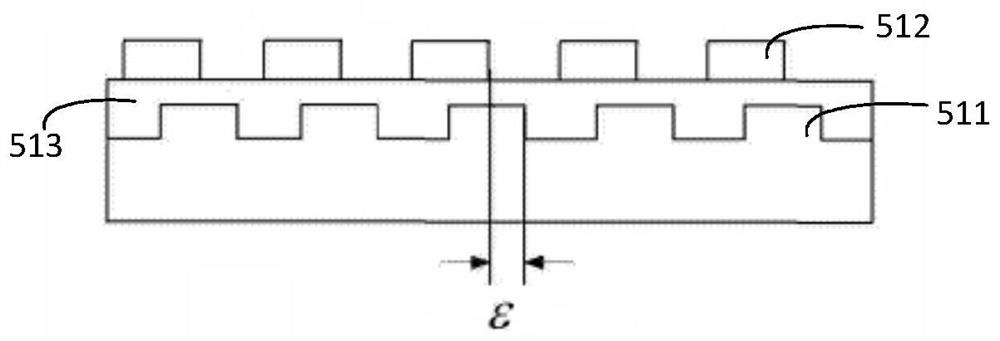
[0128] Step S1: providing an overlay mark 510, projecting the measurement light spot on the overlay mark 510, and being reflected by the overlay mark 510 to form diffracted light;

[0129] Step S2: adjust the overlay mark 510 to the first position, move the overlay mark 510 in multiple steps along the direction of the horizontal component of the measurement spot, and obta...


PUM

PropertyMeasurementUnit
Diameteraaaaaaaaaa

Abstract

The invention provides an asymmetry calibration method for overlay error measurement, which comprises the following steps of: providing an overlay mark, projecting a measurement light spot onto the overlay mark, and reflecting the measurement light spot by the overlay mark to form diffraction light; adjusting the overlay mark to a first position, moving the overlay mark along the direction of the horizontal component of the measurement light spot in a stepping manner for many times, after each stepping movement, acquiring the light intensity of diffraction light of the overlay mark, generating a first measurement signal, and taking the mean value of the first measurement signal as a first reference signal; adjusting the overlay mark to a second position, moving the overlay mark along the direction of the horizontal component of the measurement light spot step by step for multiple times, after each step movement, obtaining the light intensity of the diffraction light of the overlay mark and generating a second measurement signal, and taking the mean value of the second measurement signal as a second reference signal; and obtaining a reference signal according to the first reference signal and the second reference signal. According to the asymmetry calibration method for overlay error measurement, the overlay error measurement can be more stable.

Description

technical field [0001] The invention relates to the technical field of photolithography, in particular to a method for asymmetry calibration of overlay error measurement. Background technique [0002] According to the lithography measurement technology roadmap given by the International Technology Roadmap for Semiconductors (ITRS), as the lithography pattern critical dimension (CD) enters the 22nm and below process nodes, especially the double exposure (Double Patterning) and EUVL technology With the application and development of lithography process parameters, the measurement accuracy requirements of overlay (Overlay) of lithography process parameters have entered the sub-nanometer field. Due to the limitation of imaging resolution limit, the traditional imaging-based overlay (IBO) measurement technology based on imaging and image recognition has gradually been unable to meet the requirements of new process nodes for overlay error measurement. Diffraction-Based Overlay (D...

Claims


Application Information

Patent Timeline
IPC IPC(8): G03F7/20G03F9/00
CPCG03F7/70633G03F9/7019G03F9/7046G03F9/7049
Inventor 郑振飞管小飞
Owner SHANGHAI MICRO ELECTRONICS EQUIP (GRP) CO LTD
Why Eureka
Try Eureka