Lever system for force transmission

A lever and force transmission technology, used in grain handling and other directions to achieve the effect of good proximity

Active Publication Date: 2021-11-09
LOESCHE GMBH
View PDF16 Cites 0 Cited by
  • Summary
  • Abstract
  • Description
  • Claims
  • Application Information

AI Technical Summary

Problems solved by technology

In addition, the accessibility and operability of the components of the existing lever system integrated in the mill frame also seem to need improvement

Method used


Image

  • Lever system for force transmission
  • Lever system for force transmission
  • Lever system for force transmission

Examples


Embodiment Construction

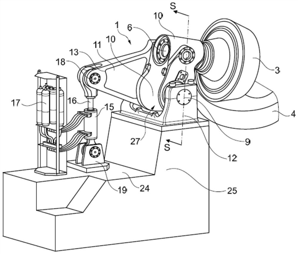
[0035] exist figure 1 The lever system 1 according to the invention is schematically shown in perspective in the direction of the corresponding grinding table 4 . The conical grinding roller 3 rolls on the grinding material to be comminuted in a non-positive and frictional manner during operation and is guided by its roller shaft 6 located in the central rocker 10 .

[0036] The central rocker 10 is arranged via the rocker shaft 9 in a U-shaped bearing block 12 , which in this example is fixed on a stepped concrete base 25 .

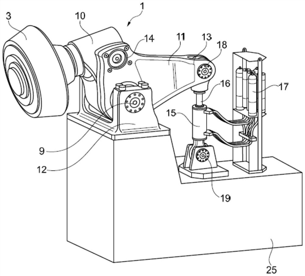
[0037]in accordance with figure 2 In a side perspective view of the lever system 1 of the present invention, the side rods 11 located in the area to the left of the central rocker 10 are firmly connected by means of flange-like fasteners 14, wherein the side rods 11 are supported on the lower part of the rocker shaft 9 in the area.

[0038] The side bars 11 having an approximately triangular or L-shaped design face with their L-shaped long sides in ...


PUM


Abstract

The invention relates to a lever system for force transmission for a grinding roller. It is intended to provide a more economical, simplified lever system which no longer needs integration into a mill stand but is more easily accessible for mounting and maintenance work. For that purpose, in particular an eccentrically arranged side lever is provided on the central swinging lever of the grinding roller, which side lever has a lever arm extending in the opposite direction to the grinding roller, and the force is transmitted to the swinging lever and the grinding roller via a lever arm of the side lever and a piston rod of the hydraulic cylinder.

Description

technical field [0001] The invention relates to a lever system for transmitting force to a grinding roller according to the preamble of claim 1 . Background technique [0002] Lever systems of this type are used especially in roller mills or vertical mills for comminuting ground materials such as cement clinker or coal. [0003] With regard to such a vertical mill, reference may be made, for example, to WO 2005 / 028112A1. [0004] exist Image 6 and 7 An example of such a lever system 50 is also shown in FIG. Image 6 The shown side perspective view shows a conical grinding roller 51 which, in operation, rolls with its grinding surfaces in a non-positive and frictional engagement on the grinding material to be comminuted. exist Image 6 and 7 The well-known grinding table with abrasive material transported thereon is not shown. [0005] The lever system 50 commonly used so far has an upwardly projecting rocker fork 53 which is supported on a rocker shaft 54 ​​and which is...

Claims


Application Information

Patent Timeline
Patent Type & Authority Applications(China)
IPC IPC(8): B02C15/04B02C15/00
CPCB02C15/004B02C15/04
Inventor 亚历山大·克罗高瓦迪克·格鲁伯托马斯·莱斯驰乔里·贝特沃斯
Owner LOESCHE GMBH
Why Eureka
Try Eureka