
Co2 separation & liquefaction system and method

A liquefaction system, CO2 technology, applied in the field of CO2 capture technology, can solve problems such as reducing the effect of system capture CO2

Active Publication Date: 2021-11-09
BRIGHT ENERGY STORAGE TECHNOLOGIES LLP
View PDF8 Cites 2 Cited by
  • Summary
  • Abstract
  • Description
  • Claims
  • Application Information

AI Technical Summary

Problems solved by technology

This means that very small leaks in the R-14 refrigerant circuit can significantly reduce the effectiveness of the system in capturing CO2

Method used


Image

  • Co2 separation & liquefaction system and method
  • Co2 separation & liquefaction system and method
  • Co2 separation & liquefaction system and method

Examples


Embodiment Construction

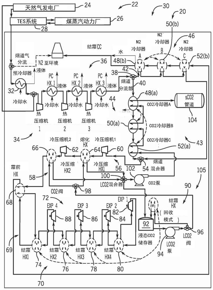
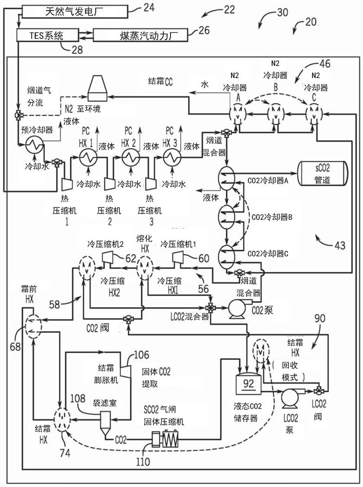
[0021] The operating environment of the present invention is described for a CO2 separation and liquefaction system for exhaust gases from fossil fuel combustion. However, those skilled in the art will appreciate that the present invention is equally applicable to the separation and liquefaction of CO2 from other carbon gas streams. While embodiments of the invention will be described with respect to carbon capture and storage systems for fossil fuel fired power plants, embodiments of the invention are equally applicable to CO2 separation and liquefaction for other industrial processes.

[0022] refer to figure 1 , according to an embodiment of the present invention, a CO2 separation and liquefaction system 20 with interstage warming expansion is shown. CO 2 separation and liquefaction system 20 is shown coupled to combined cycle power plant 22 including natural gas power plant 24 , coal steam power plant 26 , and thermal energy storage (TES) system 28 . Natural gas power pl...


PUM


Abstract

A CO2 separation and liquefaction system such as might be used in a carbon capture and sequestration system for a fossil fuel burning power plant is disclosed. The CO2 separation and liquefaction system includes a first cooling stage to cool flue gas with liquid CO2, a compression stage coupled to the first cooling stage to compress the cooled flue gas, a second cooling stage coupled to the compression stage and the first cooling stage to cool the compressed flue gas with a CO2 melt and provide the liquid CO2 to the first cooling stage, and an expansion stage coupled to the second cooling stage to extract solid CO2 from the flue gas that melts in the second cooling stage to provide the liquid CO2.

Description

[0001] Cross References to Related Applications [0002] This application is a non-provisional application of, and claims priority to, U.S. Provisional Patent Application No. 62 / 825,947, filed March 29, 2019, the disclosure of which is incorporated herein by reference in its entirety. technical field [0003] Embodiments of the present invention relate to CO 2 separation and liquefaction, and more particularly to CO 2 capture technology using exhaust gas as a refrigerant to liquefy CO 2 and separate CO 2 from exhaust gas. Background technique [0004] The scientific community generally agrees that global climate change, or global warming, is the result of CO2 emissions from human activities. The main source of CO2 emissions is the burning of fossil fuels for energy production. To slow the rise in global temperatures, society must reduce the amount of CO2 emitted into the atmosphere as our demand for energy increases. One way to reduce CO2 emissions is to capture the CO2 th...

Claims


Application Information

Patent Timeline
Patent Type & Authority Applications(China)
IPC IPC(8): F25J3/06F25J1/00B01D53/62
CPCF25J3/067F25J2205/20F25J2210/06F25J2210/70F25J3/066F25J2220/82F25J2230/08F25J2230/30F25J2260/80F25J2270/06F25J2235/80F25J2270/02F25J2230/04F25J2280/30B01D53/002F25J2210/40F25J2270/904F25J2270/16F25J2240/10F25J2230/40B01D2258/0283B01D2257/504Y02C20/40F25J2220/80F25J3/0266F25J2270/80F25J2230/02F25J2240/40F25J2220/66
Inventor 迈尔斯·L·阿巴拉斯科特·雷蒙德·弗雷泽
Owner BRIGHT ENERGY STORAGE TECHNOLOGIES LLP
Features
  • Generate Ideas
  • Intellectual Property
  • Life Sciences
  • Materials
  • Tech Scout
  • Unparalleled Data Quality
  • Higher Quality Content
  • 60% Fewer Hallucinations
Learn More