Breathing machine with return air treatment function

A technology of ventilator and connected components, applied in the medical field, can solve problems such as inability to adjust ventilation volume

Inactive Publication Date: 2021-11-12
李青林
View PDF1 Cites 0 Cited by
  • Summary
  • Abstract
  • Description
  • Claims
  • Application Information

AI Technical Summary

Problems solved by technology

[0002] For example, the patent number is CN201820054587.8, a ventilator for emergency department, which includes a ventilator body and an elastic oxygen delivery tube. A liquid crystal display is fixedly installed in the middle of the front outer surface of the ventilator body, and the bottom of the liquid crystal display is close to the breathing apparatus. An oxygen concentration adjustment knob is movably installed on one end of the outer surface of the ventilator body, and a circuit board is fixedly installed inside the ventilator body. One end is fixedly equipped with an oxygen delivery hole, and one end of the ventilator body near the oxygen delivery hole is provided with an oxygen bottle connection, but the disadvantage of this technical solution is that the ventilation volume cannot be adjusted

Method used


Image

  • Breathing machine with return air treatment function
  • Breathing machine with return air treatment function
  • Breathing machine with return air treatment function

Examples


specific Embodiment approach 1

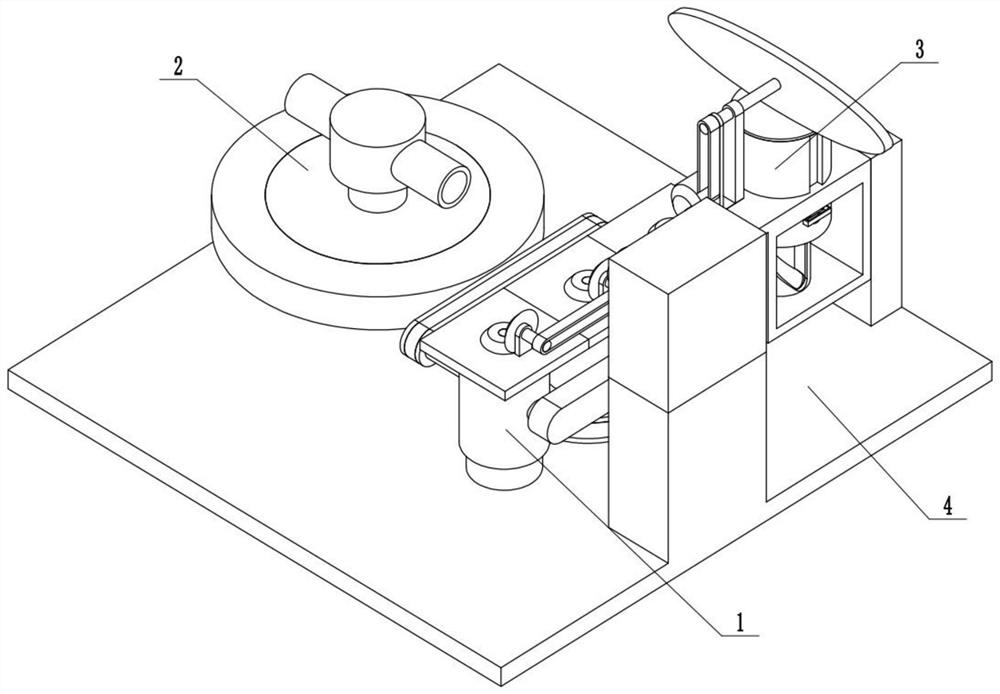
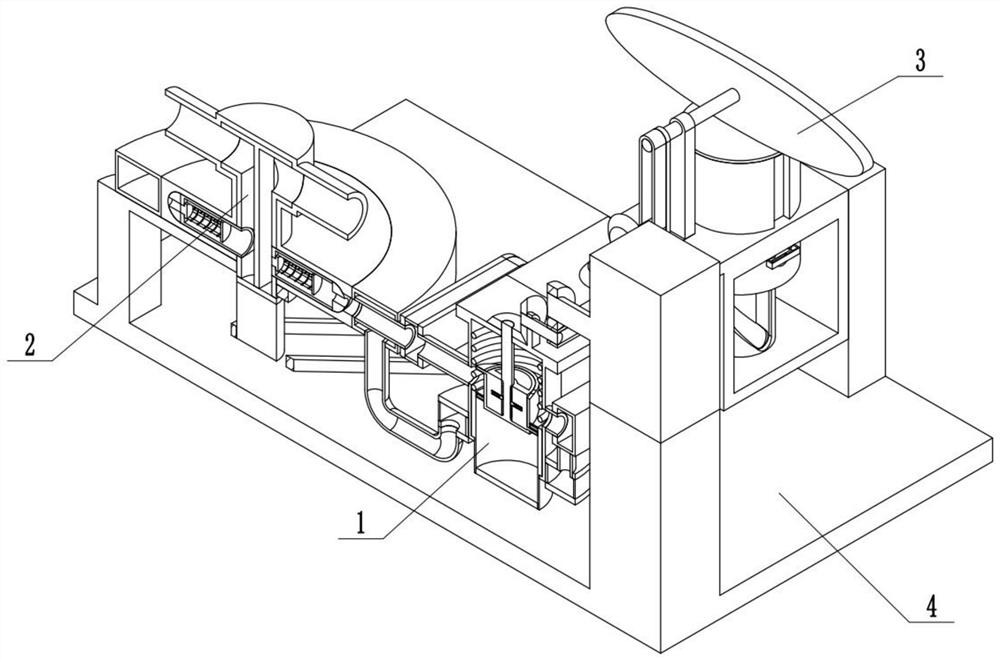
[0032] Combine below Figure 1-15 Describe this embodiment, a ventilator with return air treatment, including a breathing cylinder assembly 1, a communication assembly 2, an exchange drive assembly 3, and a power assembly 4. The breathing cylinder assembly 1 is connected to a communication assembly 2, and the communication assembly 2 It is connected with the exchange drive assembly 3 , the exchange drive assembly 3 is connected with the power assembly 4 , the breathing cylinder assembly 1 is connected with the power assembly 4 , and the communication assembly 2 is connected with the power assembly 4 .

specific Embodiment approach 2

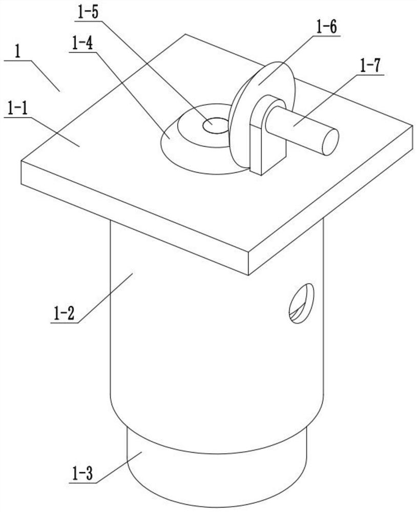
[0033] Combine below Figure 1-15 Describe this embodiment, this embodiment will further explain the first embodiment, the breathing cylinder assembly 1 includes a mounting plate 1-1, a cylinder 1-2, a piston cylinder 1-3, a bevel tooth 1-4, a bevel tooth Shaft 1-5, bevel gear 2 1-6, bevel gear shaft 2 1-7, drive inner sleeve 1-8, inner expansion sleeve 1-9, inner push spring 1 1-10, cooperating roller 1-11, the inner end clamping rod one 1-12, the inner end clamping rod push spring one 1-13, the inner end clamping groove one 1-14, the screw rod one 1-15, the screw rod two 1-16, the installation Plate 1-1 is fixedly connected with cylinder body 1-2, piston cylinder body 1-3 is connected with sliding fit with cylinder body 1-2, bevel gear one 1-4 is fixedly connected with bevel gear shaft one 1-5, bevel gear shaft one 1-5 is rotationally connected with mounting plate 1-1, bevel gear 2 1-6 is engaged with bevel gear 1 1-4 for meshing transmission, bevel gear 2 1-6 is fixedly co...

specific Embodiment approach 3

[0035] Combine below Figure 1-15 Describe this embodiment, this embodiment will further explain the first embodiment, the communication assembly 2 includes an annular communication pipe 2-1, a middle outer frame 2-2, an upper connecting pipe 2-3, a connecting pipe 2-4, Connecting pipe two 2-5, connecting pipe three 2-6, connecting pipe four 2-7, connecting pipe five 2-8, connecting pipe six 2-9, connecting pipe seven 2-10, inner casing one 2-11 , Connecting cavity 1 2-12, Connecting cavity 2 2-13, Connecting hole 1 2-14, Connecting hole 2 2-15, Connecting pipe 1 2-16, Inner pusher 1 2-17, Inner connecting sleeve One 2-18, rectangular through hole one 2-19, inner end push spring one 2-20, inner end pusher two 2-21, connecting tube two 2-22, rectangular through hole two 2-23, inner end push spring Two 2-24, the inner connecting pipe A2-25, the inner connecting sleeve two 2-26, the middle outer frame 2-2 is fixedly connected with the annular connecting pipe 2-1, and the upper c...


PUM


Abstract

The invention relates to the field of medical treatment, in particular to a breathing machine with a return air treatment function. And the maximum ventilation amount can be adjusted according to actual conditions. The breathing machine comprises a breathing cylinder assembly, a communicating assembly, an exchange driving assembly and a power assembly; the breathing cylinder assembly is connected with the communicating assembly; the communicating assembly is connected with the exchange driving assembly; the exchange driving assembly is connected with the power assembly; the breathing cylinder assembly is connected with the power assembly; and the communicating assembly is connected with the power assembly. An inner-end sleeve and an inner-end expansion sleeve can be relatively rotated and driven, so that a second screw rod slides along a first screw rod, the use length of the first screw rod is expanded, the total stroke of reciprocating motion of a piston cylinder body is changed, and the maximum amount of gas capable of being contained in the piston cylinder body is changed.

Description

technical field [0001] The invention relates to the medical field, in particular to a ventilator with return air treatment. Background technique [0002] For example, the patent number is CN201820054587.8, a ventilator for emergency department, including a ventilator body and an elastic oxygen delivery tube, a liquid crystal display is fixedly installed in the middle of the front outer surface of the ventilator body, and the bottom of the liquid crystal display is close to the breathing apparatus. An oxygen concentration adjustment knob is movably installed on one end of the outer surface of the ventilator body, and a circuit board is fixedly installed inside the ventilator body. One end is fixedly equipped with an oxygen delivery hole, and one end of the ventilator body close to the oxygen delivery hole is provided with an oxygen cylinder connecting pipe, but the disadvantage of this technical solution is that the ventilation volume cannot be adjusted. Contents of the inv...

Claims


Application Information

Patent Timeline
Patent Type & Authority Applications(China)
IPC IPC(8): A61M16/00A61M16/22
CPCA61M16/00A61M16/0003A61M16/22
Inventor 李青林
Owner 李青林
Why Eureka
Try Eureka