Suction filtration experiment device and method

An experimental device and filter paper technology, applied in separation methods, chemical instruments and methods, filtration and separation, etc., can solve the problems that affect the accurate reading of filtrate volume, affect the accuracy of reading, and filter paper is easy to hang pulp, etc., which is conducive to accurate measurement. Effect

Active Publication Date: 2021-11-12
林哲鑫
View PDF36 Cites 0 Cited by
  • Summary
  • Abstract
  • Description
  • Claims
  • Application Information

AI Technical Summary

Problems solved by technology

[0006] The inventor found that the difficulty of the prior art is that the surprise control of the vacuum filtration device relies on the fine control of the vacuum pump, which requires the cooperation of multiple people, which also causes the following specific defects:
[0007] 1. When measuring, two or more people are required to cooperate together, and manual reading is required; the reading accuracy is low
[0008] 2. Since the measuring device currently used is generally a graduated cylinder, t

Method used


Image

  • Suction filtration experiment device and method
  • Suction filtration experiment device and method
  • Suction filtration experiment device and method

Examples


Embodiment 1

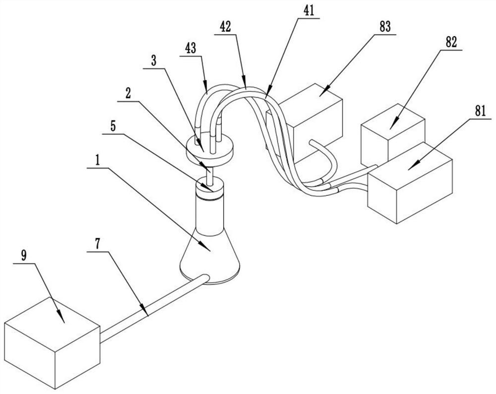
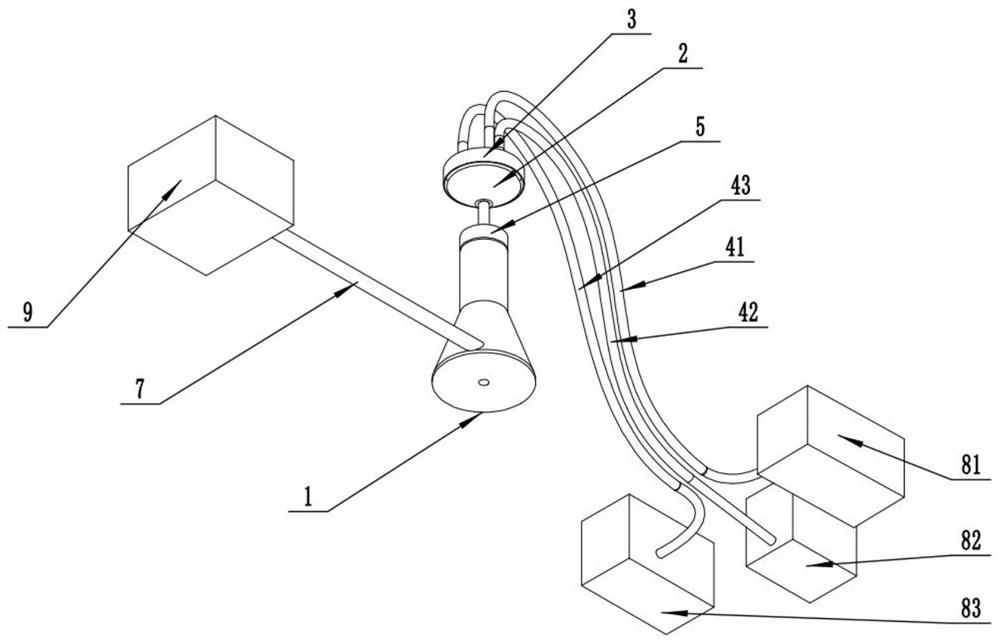
[0051] In a typical implementation of the present invention, this embodiment discloses a suction filtration experimental device, comprising:

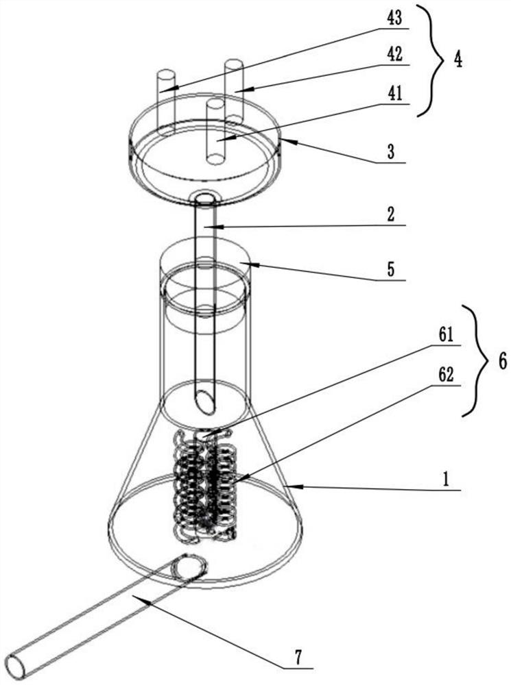
[0052] The bottle body 1 has a cavity inside, an opening is opened on the top, and the bottle stopper 5 is detachably connected to the opening;

[0053] Funnel 2, the top opening is laid with filter paper, and the bottom opening passes through the bottle stopper 5 and enters the bottle body 1;

[0054] The pressurized container 3 is provided with a detachable cover on the top of the funnel 2, and can close the top of the funnel 2. The pressurized container 3 is provided with a plurality of pressurized gas inlets, and each pressurized gas inlet is respectively connected to a pressure source 8;

[0055] The negative pressure source 9 is connected to the bottle body 1;

[0056] The measuring pipe 6 with the main body in a spiral shape is arranged in the bottle body 1, the entrance of the measuring pipe 6 is located directly below the funn...

Embodiment 2

[0083] In a typical implementation of the present invention, this embodiment discloses a suction filtration experimental method, using the suction filtration experimental device as described in Example 1, comprising the following steps:

[0084] Assemble the suction filtration experimental device, and keep the top opening of the funnel 2 open;

[0085] Put the sludge on the filter paper;

[0086] The pressurized container 3 is covered and connected to the top opening of the funnel 2;

[0087] start the server;

[0088] According to the experimental requirements, select any one or several of the first pressure source 81 to the third pressure source 83, and start the pressure source 8;

[0089] Start negative pressure source 9;

[0090] Take the reading from the server; or take the reading manually.


PUM

PropertyMeasurementUnit
Central angleaaaaaaaaaa

Abstract

The invention discloses a suction filtration experiment device and method, and belongs to the technical field of buildings. A capillary tube is used, and ripple fluctuation can be prevented from being generated in the process of gathering liquid drops into a measuring cylinder, so that the measurement accuracy is enhanced. The device comprises a bottle body, a funnel, a pressurizing container, a negative pressure source, a measuring pipeline and a server, wherein the bottle body is internally provided with a cavity, and an opening is formed in the top of the bottle body and detachably connected with a bottle plug; a top opening of the funnel is paved with filter paper, and a bottom opening penetrates through the bottle plug and enters the bottle body; the pressurizing container detachably covers the top end of the funnel and can seal the top end of the funnel, the pressurizing container is provided with a plurality of pressurized gas inlets, and each pressurized gas inlet is communicated with a pressure source; the negative pressure source is communicated with the bottle body; a main body of the measuring pipeline is spiral, the measuring pipeline is arranged in the bottle body, an inlet of the measuring pipeline is located under the funnel, and the measuring pipeline is further provided with a water level measuring device for measuring the water level; and the water level measuring device can communicate with the server.

Description

technical field [0001] The invention belongs to the technical field of construction, and in particular relates to a suction filtration experiment device and method. Background technique [0002] Municipal sludge is a gelatinous waste produced in the process of sewage treatment in municipal sewage treatment plants. Random discharge and stacking of untreated sludge will cause serious environmental problems. International sludge disposal methods mainly include land use, sanitary landfill, incineration, sea throwing, etc. Among them, landfill disposal has relatively loose requirements on technical indicators and low operating costs, and is the main method of sludge disposal at this stage. The simple separate landfill means that after the sludge is dehydrated and digested, it is directly dumped into the pre-set landfill pit to form a temporary sludge storage area. [0003] The inventors found that the sludge has a high water content and poor physical and mechanical properties, w...

Claims


Application Information

Patent Timeline
IPC IPC(8): B01D29/085
CPCB01D29/085
Inventor 林哲鑫
Owner 林哲鑫
Why Eureka
Try Eureka