Supercharge Your Innovation With Domain-Expert AI Agents!

Pintle chain automatic assembling device and assembling method thereof

A technology of automatic assembly device and pinning chain, applied in the direction of metal chain, etc., can solve the problems of low efficiency and labor consumption, and achieve the effect of high degree of automation, improved quality and reasonable design

Pending Publication Date: 2021-11-12
安徽黄山中友链条制造有限公司
View PDF13 Cites 0 Cited by
  • Summary
  • Abstract
  • Description
  • Claims
  • Application Information

AI Technical Summary

Problems solved by technology

[0005] The purpose of the present invention is to solve the problems of labor-intensive and low efficiency in the prior art, and propose a pin-joint chain automatic assembly device and its assembly method

Method used


Image

  • Pintle chain automatic assembling device and assembling method thereof
  • Pintle chain automatic assembling device and assembling method thereof

Examples


Embodiment 1

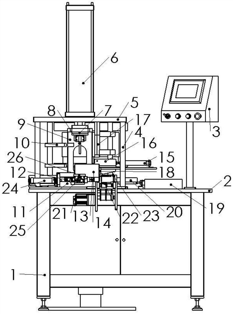
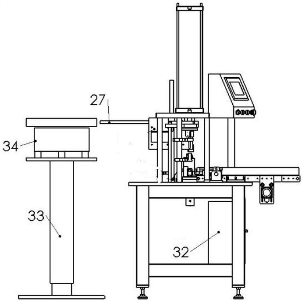
[0029] refer to Figure 1-2 , an automatic assembly device for pin-joint chains, comprising a work frame 1, a workbench 2 is fixed on the upper end of the workbench 1, a control panel 3 is installed on one side of the top surface of the workbench 2, and a vibration plate support 33 is placed on the rear side 33 is fixed with a vibrating plate 34, the output end of the vibrating plate 34 is fixedly connected with a feeding pipe 27, an electrical box 32 is arranged in front of the work frame 1, and a column 4 is installed on the workbench 2, and the column 4 is provided with four and is rectangular. Distributed on the workbench 2, a hydraulic cylinder installation table 5 is fixed on the top of the column 4, a hydraulic cylinder 6 is fixed on the hydraulic cylinder installation table 5, and the output end of the hydraulic cylinder 6 is connected with a flange 7 and a flange 7 by screws. A thimble 8 and a positioning base part 9 are fixed, guide rails 10 are provided on both side...

Embodiment 2

[0032] This embodiment is basically the same as Embodiment 1, preferably, the assembly method of the device

[0033] S1. Put the pin shaft on the vibrating plate 34. After the vibrating plate 34 is started, the pin shaft will be automatically put in place through the feeding pipe 27 and the feeding steering member 17, and the chain link workpiece will be placed on the conveyor belt 22 and automatically transported in place, and the signal will be fed back to the system.

[0034] S2. The signal of the system feeding chain link cylinder 19 is closed, the pushing cylinder is in place, the signal is fed back to the system, the signal of the system feeding chain link cylinder 19 is disconnected, the pushing cylinder returns to the position, and the signal is fed back to the system.

[0035] S3. The system sends a signal to the pin delivery cylinder 15 to close, the push cylinder is in place, the signal is fed back to the system, the system sends a signal to the pin delivery cylinder...


PUM


Abstract

The invention discloses a pintle chain automatic assembling device which comprises a working frame. A working table is fixed to the upper end of the working frame, a control panel is installed on one side of the top face of the working table, a vibration disc support is arranged on the rear side of the working table, a vibration disc is fixed to the upper portion of the vibration disc support, and the output end of the vibration disc is fixedly connected with a feeding pipe. An electrical box is arranged in front of the working frame, a stand column is installed on the working table, a hydraulic cylinder installation table is fixed to the top end of the stand column, a hydraulic cylinder is fixed to the hydraulic cylinder installation table, the output end of the hydraulic cylinder is connected with a flange plate through screws, an ejector pin and a positioning basic part are fixed to the flange plate, guide rails are arranged on the two sides of the positioning basic part, and a feeding steering part and a feeding pipe are arranged on one side of the positioning basic part. The pintle chain automatic assembling device is reasonable in design, stable in device operation and high in automation degree, and positioning of a shaft pin and a chain link during assembly is accurate, so that the quality of batch production of pintle chains is well guaranteed.

Description

technical field [0001] The invention relates to the technical field of production equipment for pin-joint chains, in particular to an automatic assembly device for pin-joint chains and an assembly method thereof. Background technique [0002] The pin-joint chain refers to a chain whose links are made of malleable cast iron and connected by steel pins. There is no distinction between inner and outer links. When the pin-joint chain is processed, it needs to be assembled, which requires an automatic assembly device. [0003] After retrieval, the patent with application number 201621123342.3 discloses an automatic assembly device for chain pins, which is composed of a lower mold body, a cover plate, a stepping motor, a pin magnetic turntable, a cylinder and an upper mold body, and is characterized in that the middle part of the lower mold body A backing plate is installed, a cover plate is installed on the top of the backing plate, a chain warehouse is installed on the upper lef...

Claims


Application Information

Patent Timeline
IPC IPC(8): B21L9/06
CPCB21L9/065B21L9/06
Inventor 许敏江海涛方丹唐凯
Owner 安徽黄山中友链条制造有限公司
Features
  • R&D
  • Intellectual Property
  • Life Sciences
  • Materials
  • Tech Scout
  • Unparalleled Data Quality
  • Higher Quality Content
  • 60% Fewer Hallucinations
Learn More