Gun head machining equipment

A technology for processing equipment and gun heads, applied in metal processing equipment, metal processing, metal processing mechanical parts, etc., can solve the problems of low processing efficiency and a large number of operators, improve production efficiency, reduce labor costs, and reduce errors. small effect

Pending Publication Date: 2021-11-12
LINHAI CITY RAUL MACHINE
View PDF0 Cites 0 Cited by
  • Summary
  • Abstract
  • Description
  • Claims
  • Application Information

AI Technical Summary

Problems solved by technology

[0004] Aiming at the above-mentioned problems in the prior art that each processing step of processing the tip of an air gun needs to be carried out separately, the number of operators required is large, and the processing efficiency is low, the present application provides a processing equipment for the tip of a gun

Method used


Image

  • Gun head machining equipment
  • Gun head machining equipment

Examples


Embodiment 1

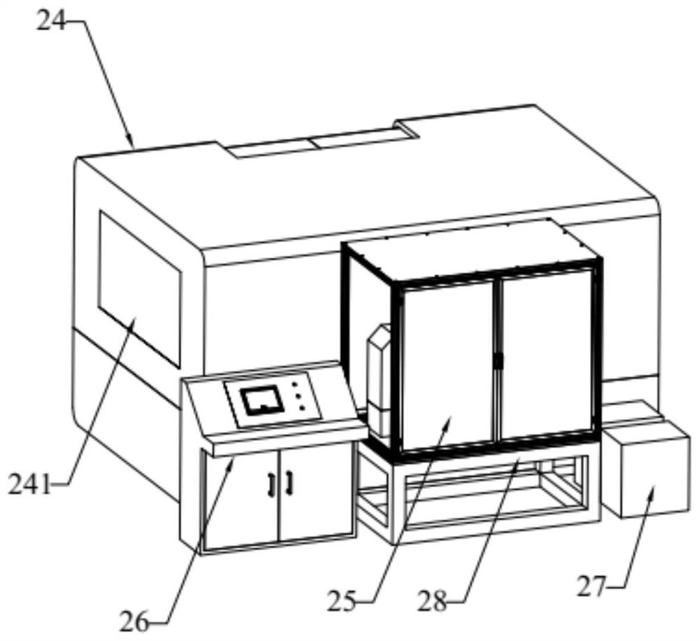
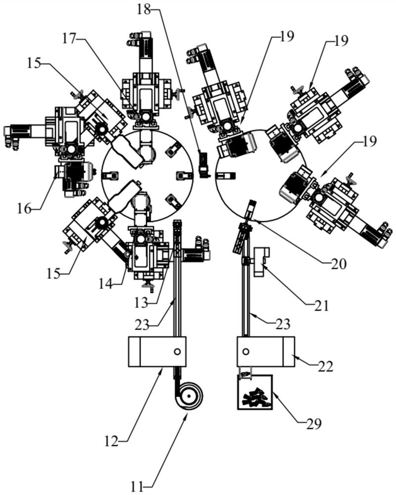
[0026] Such as Figure 1 to Figure 2 Shown is a gun tip processing equipment 10 of the present invention, including: a punch base 28 . The punch base 28 is provided with along the circumference of the punch base 28 in sequence: a vibrating feeding tray 11, a reverse punching burr assembly 12, a turntable feeding assembly 13, a first milling cutter assembly 14, an expanding thread assembly 15, a second milling assembly The cutter head assembly 16 , the third milling cutter head assembly 17 , the conversion disk assembly 18 , the fourth milling cutter head assembly 19 , the turntable blanking assembly 20 , the middle groove deburring assembly 21 and the front punching groove assembly 22 . The vibrating feeding plate 11 is used for vibrating feeding on the gun head, the reverse side punching and burring assembly 12 is used for punching and burring the reverse side of the gun head, the turntable feeding assembly 13 is used for feeding the gun head, and the first milling cutter dis...


PUM


Abstract

The invention discloses gun head machining equipment. The gun head machining equipment comprises a punch press base, wherein a vibration feeding plate, a reverse burr punching assembly, a turntable feeding assembly, a first milling cutter disc assembly, a thread expanding and tapping assembly, a second milling cutter disc assembly, a third milling cutter disc assembly, a conversion disc assembly, a middle groove rough milling device, a fourth milling cutter disc assembly, a turntable discharging assembly, a middle groove deburring assembly and a positive notching assembly are sequentially arranged on the punch press base in the circumferential direction of the punch press base ; and the vibration feeding plate, the reverse burr punching assembly, the turntable feeding assembly, the first milling cutter disc assembly, the thread expanding and tapping assembly, the second milling cutter disc assembly, the third milling cutter disc assembly, a conversion disc assembly, the fourth milling cutter disc assembly, the turntable discharging assembly, the middle groove deburring assembly and the positive notching assembly are connected at a time through a conveyor belt, so that gun heads can be conveyed and operated at a time. The equipment has the advantages that the labor cost is reduced, the equipment is high in precision, small in error, high in speed and high in stability, and the production efficiency is greatly improved.

Description

technical field [0001] The invention relates to the technical field of gun head processing, in particular to a gun head processing equipment. Background technique [0002] In the prior art, each processing step of processing the tip of the air gun needs to be carried out separately, which requires a large number of operators and low processing efficiency. Contents of the invention [0003] 1. The technical problem to be solved by the invention [0004] In view of the above-mentioned problems in the prior art that each processing step of processing the tip of an air gun needs to be carried out separately, the number of operators required is large, and the processing efficiency is low, the present application provides a tool tip processing equipment. [0005] 2. Technical solution [0006] In order to solve the above problems, the technical solution provided by the invention is: [0007] A gun head processing equipment, comprising: a punch base; along the circumferential ...

Claims


Application Information

Patent Timeline
Patent Type & Authority Applications(China)
IPC IPC(8): B23P23/04B23Q7/02B23Q7/00B23Q11/00B23Q11/08B65G47/14
CPCB23P23/04B23Q7/02B23Q7/00B23Q11/0096B23Q11/08B65G47/1421
Inventor 潘吕建
Owner LINHAI CITY RAUL MACHINE
Why Eureka
Try Eureka