A board color correction positioning device based on wooden furniture manufacturing
A positioning device, wooden furniture technology, applied in the direction of manufacturing tools, grinding/polishing safety devices, machine tools suitable for grinding workpiece planes, etc., can solve problems such as inability to guarantee the plate, reduce the consistency of the plate, and reduce work efficiency , to achieve the effect of avoiding frequent disassembly, improving color correction accuracy and improving work efficiency
- Summary
- Abstract
- Description
- Claims
- Application Information
AI Technical Summary
Problems solved by technology
Method used
Image
Examples
Embodiment 1
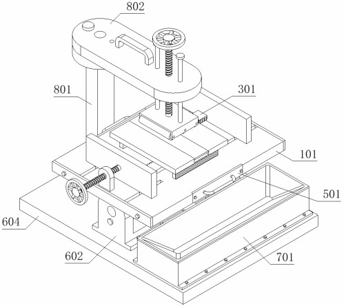
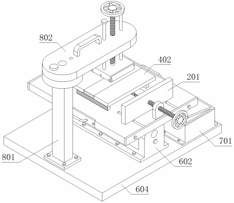
[0052] as attached figure 1 to the attached Figure 11 Shown: the present invention provides a plate color correction positioning device based on wooden furniture, comprising an installation mechanism 1; a clamping part 2 and a supporting device 4 are installed on the top of the installation mechanism 1, and a connection is installed on the clamping part 2 Assembly 3; Fixing mechanism 5, the fixing mechanism 5 is provided with two groups, and the two groups of fixing mechanisms 5 are installed inside the installation mechanism 1, and the bottom of the installation mechanism 1 is installed with an adjustment mechanism 6; The top of the adjustment mechanism 6 is installed with a collection device 7 and the pressing assembly 8, and the pressing assembly 8 is located on the left side of the collecting device 7.
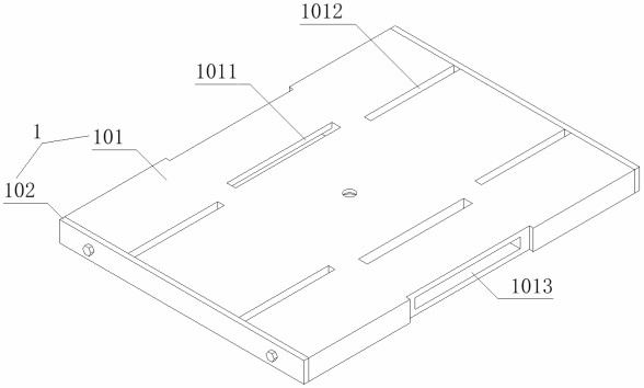
[0053] like Figure 3 to Figure 6 As shown, the installation mechanism 1 includes: an installation block 101, two connecting grooves 1011 are formed through the inside ...
Embodiment 2
[0056] like Figure 12 and Figure 13 As shown, this embodiment adds an adjusting mechanism 6 on the basis of the first embodiment. The adjusting mechanism 6 includes: a connecting block 601, the connecting block 601 is fixedly connected with the mounting block 101, and the front side of the connecting block 601 is provided with two fixing grooves 6011, and the outer wall of the connecting block 601 is fixedly installed with a tooth block 6012; the mounting seat 602, the mounting seat 602 is rotatably installed on the bottom of the connecting block 601; the fixing pin 603, the fixing pin 603 is slidably installed inside the mounting seat 602, and the fixing pin The rear end of 603 is inserted and connected in the fixing groove 6011; the bottom plate 604, the bottom plate 604 is fixedly installed at the bottom of the mounting seat 602, and its specific function is: because the mounting seat 602 is rotated and installed at the bottom of the connecting block 601, so that when the...
Embodiment 3
[0058] like Figure 14 As shown, this embodiment adds a collecting device 7 on the basis of the second embodiment. The collecting device 7 includes: a collecting box 701, which is fixedly connected with the bottom plate 604; a duct 702, which is installed on the collecting box 701 The top of the rack; the tooth row 703, the tooth row 703 is slidably installed inside the collection box 701, and the tooth row 703 is meshed with the tooth block 6012; the baffle plate 704, the baffle plate 704 is fixedly installed on the right side of the tooth row 703, its specific function Because the collection box 701 is fixedly connected to the bottom plate 604, it is convenient to collect the residue and dust after grinding, and it is convenient for the staff to deal with it in a centralized manner, and because the top of the collection box 701 is installed with a shroud 702, and the inside of the collection box 701 is slidably installed There is a tooth row 703, and a baffle plate 704 is fi...
PUM
 Abstract
Description
Claims
Application Information
 - R&D
- Intellectual Property
- Life Sciences
- Materials
- Tech Scout
- Unparalleled Data Quality
- Higher Quality Content
- 60% Fewer Hallucinations
Browse by: Latest US Patents, China's latest patents, Technical Efficacy Thesaurus, Application Domain, Technology Topic, Popular Technical Reports.
© 2025 PatSnap. All rights reserved.Legal|Privacy policy|Modern Slavery Act Transparency Statement|Sitemap|About US| Contact US: help@patsnap.com


