
Double-gate-plate wedge gate valve

A double ram and wedge technology, applied in sliding valves, valve details, valve devices, etc., can solve problems such as unreliable sealing and failure to meet the requirements of use.

Pending Publication Date: 2021-11-12
JIANGSU SHENGTAI VALVE CO LTD
View PDF0 Cites 1 Cited by
  • Summary
  • Abstract
  • Description
  • Claims
  • Application Information

AI Technical Summary

Problems solved by technology

[0003] In order to effectively cut off the fluid in the pipeline, a gate valve will be installed on the pipeline. Due to the complexity of the pipeline and the high pressure in the pipeline, the requirements for the gate valve are also very high. Most of the existing gate valves only pass through a This type of drive controls the closing of the gate, which will easily lead to unreliable sealing and cannot well meet the requirements of use.

Method used


Image

  • Double-gate-plate wedge gate valve
  • Double-gate-plate wedge gate valve
  • Double-gate-plate wedge gate valve

Examples


Embodiment 1

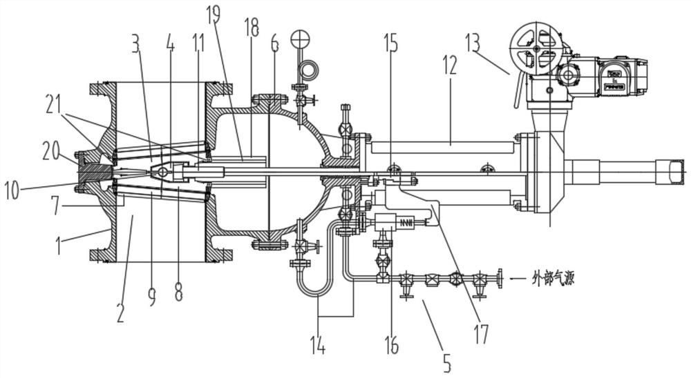
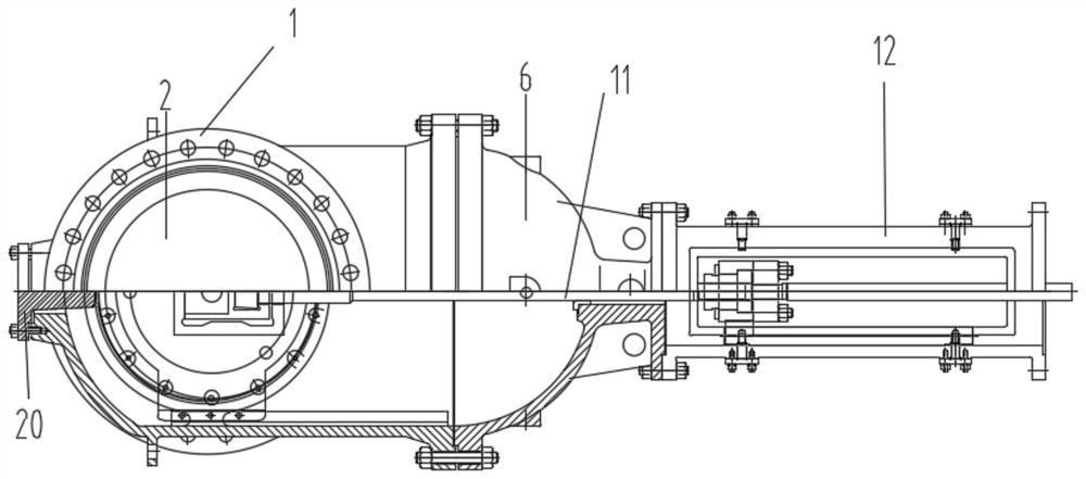
[0047] see Figure 1-2 , an embodiment provided by the present invention: a double gate wedge gate valve, characterized in that it includes: a valve body 1, a flow channel 2, a closing member 3, a driving member 4, a bypass assembly 5, and a valve cover 6;

[0048] The flow channel 2 is arranged inside the valve body 1, the closing member 3 is used to control the opening and closing of the flow channel 2, and the driving member 4 is used to provide driving power for the action of the closing member 3, The right end of the valve body 1 is provided with the valve cover 6, the bypass assembly 5 is arranged outside the valve cover 6 and connected with the valve cover 6, the bypass assembly 5 is used to control the external air source The low-pressure inert gas is input into the valve cover 6 , and then linked with the driver 4 to control the closing of the flow channel 2 in the valve body 1 .

[0049] Preferably, the upper and lower ends of the valve body 1 are respectively an in...

Embodiment 2

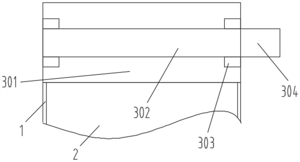
[0063] refer to Figure 3-4 , On the basis of the above-mentioned embodiment 1, a filter device is also provided at the inlet end of the upper end of the valve body 1, and the filter device is fixed with the valve body 1, and the filter device includes: a filter device housing 301, filter assembly 302, limit chute 303, filter replacement device 304;

[0064] The filtering device housing 301 is fixed to the inlet end of the valve body 1, the inner side wall of the filtering device housing 301 is fixed with the limiting chute 303, and the filter screen assembly 302 is slidably connected to the limiting In the chute 303 , the filter housing 301 is provided with a filter replacement device 304 , and the filter replacement device 304 is connected to the filter assembly 302 .

[0065] Preferably, the filter replacement device 304 includes:

[0066] Guide plate 30401, first slider 30402, first chute 30403, rebound power arm 30404, spring connection hole 30405, first linkage plate 3...

Embodiment 3

[0078] refer to Figure 5-7 , On the basis of the above-mentioned embodiment 1, a flow channel change detection device is also provided at the outlet end of the lower end of the valve body 1, and the flow channel change detection device includes:

[0079] Circulation cavity 401, power chamber 402, rotating force arm 403, motor 404, transmission shaft 405, driving gear 406, ring gear 407, fifth fixed shaft 408, seventh hinged shaft 409, detection board 410, fixed bottom plate 411, Limiting tube 412, second chute 413;

[0080] One side of the circulation cavity 401 is fixed to the outlet end of the lower end of the valve body 1, the power compartment 402 is in a ring structure, the circulation cavity 401 is between the power compartments 402, and the power compartment 402 The motor 404 is fixed on the inner wall of 402, and the motor 404 is electrically connected to the power controller. The seven articulated shafts 409 are rotating, while the motor 404 is still running, and a...


PUM


Abstract

The invention discloses a double-gate-plate wedge gate valve. The double-gate-plate wedge gate valve comprises a valve body, a flow channel, a closing part, a driving part, a bypass assembly and a valve deck. The flow channel is formed in the valve body, the closing part is used for controlling opening and closing of the flow channel, the driving part is used for providing driving power for action of the closing part, the valve deck is arranged at the right end of the valve body, the bypass assembly is arranged outside the valve deck, connected with the valve deck and used for controlling an external gas source to input low-pressure inert gas into the valve deck, and the valve deck is further linked with the driving part to control closing of the flow channel in the valve body. The double-gate-plate wedge gate valve is provided with a double-gate-plate structure, and bidirectional forced sealing can be achieved; when the valve is opened and closed, only the friction force at the inclined surface of a wedge block needs to be overcome, and gate plates can flexibly move after the wedge block moves; and when the valve is closed, the external gas source is controlled through valve rod limiting to input the low-pressure inert gas to assist in sealing, and when the valve is opened, input of the external gas source is controlled through valve rod limiting to be cut off.

Description

technical field [0001] The invention relates to the field of gate valves, in particular to a double gate wedge gate valve. Background technique [0002] The gate valve is a gate of the opening and closing part. The direction of movement of the gate is perpendicular to the direction of the fluid. The gate valve can only be fully opened and fully closed, and cannot be adjusted or throttled. The gate valve is sealed by the contact between the valve seat and the gate plate. Usually, the sealing surface will be surfacing with metal materials to increase wear resistance, such as surfacing welding 1Cr13, STL6, stainless steel, etc. There are rigid gate valves and elastic gate valves. According to the different gate valves, gate valves are divided into rigid gate valves and elastic gate valves. . [0003] In order to effectively cut off the fluid in the pipeline, a gate valve will be installed on the pipeline. Due to the complexity of the pipeline and the high pressure in the pipe...

Claims


Application Information

Patent Timeline
Patent Type & Authority Applications(China)
IPC IPC(8): F16K3/14F16K3/30F16K3/314F16K3/316F16K27/04F16K31/12F16K37/00B01D35/04
CPCF16K3/14F16K3/30F16K3/314F16K3/316F16K27/047F16K31/12F16K37/0083F16K37/0091B01D35/04
Inventor 李伟严涛严珊珊童海东
Owner JIANGSU SHENGTAI VALVE CO LTD
Learn More