Material mixing device for ceramic clay manufacturing

A mixing device and clay technology, applied in the field of clay mixing, can solve the problems of poor control of the input time of mixing materials, uneven clay firing, etc., and achieve the effect of sufficient combustion

Pending Publication Date: 2021-11-12
XINYI XIYI ADVANCED MATERIALS RES INST OF IND TECH CO LTD
View PDF0 Cites 0 Cited by
  • Summary
  • Abstract
  • Description
  • Claims
  • Application Information

AI Technical Summary

Problems solved by technology

[0003] The technical problem to be solved by the present invention is that when traditional ceramic clay is fired, it is not easy to control the input time of mixing materials, which may easily cause uneven firing of clay.

Method used


Image

  • Material mixing device for ceramic clay manufacturing
  • Material mixing device for ceramic clay manufacturing
  • Material mixing device for ceramic clay manufacturing

Examples


Embodiment 1

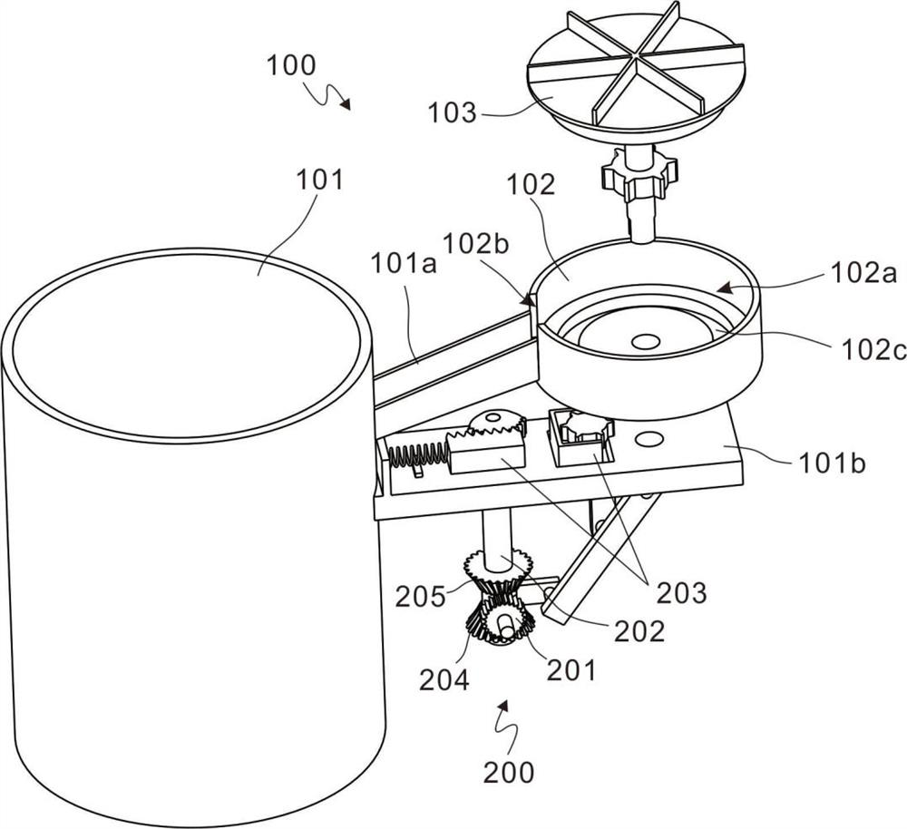
[0022] refer to figure 1 , figure 2 , is the first embodiment of the present invention, which provides a mixing device for ceramic clay production, including a mixing assembly 100 and a driving assembly 200 .

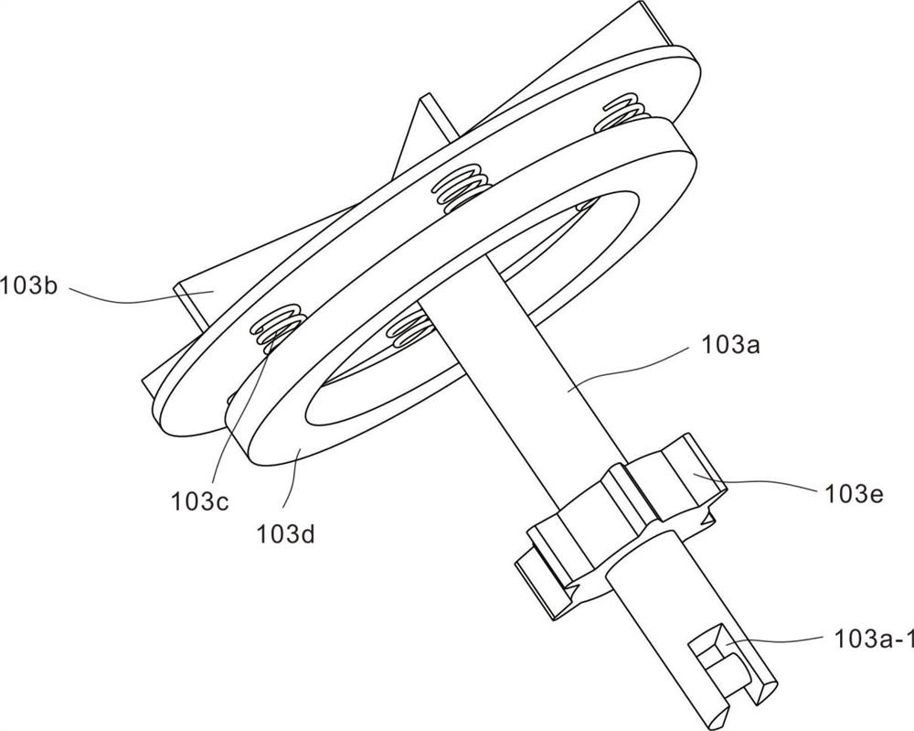
[0023] The mixing assembly 100 includes a melting furnace 101, a feeding tray 102 and a steering wheel 103. An inclined slideway 101a is provided on the outer wall of the melting furnace 101, and the sliding path 101a is connected to the feeding tray 102, and the steering wheel 103 is installed in the feeding tray 102 and Can rotate in the feeding tray 102. A mounting plate 101 b is disposed on the outer wall of the melting furnace 101 , and the mounting plate 101 b extends toward the bottom of the feeding tray 102 . A round shaft 103a is provided at the bottom of the steering wheel 103, and the round shaft 103a passes through the feeding tray 102 and is connected to the mounting plate 101b.

[0024] The top surface of the steering plate 103 has a tendency to inclin...

Embodiment 2

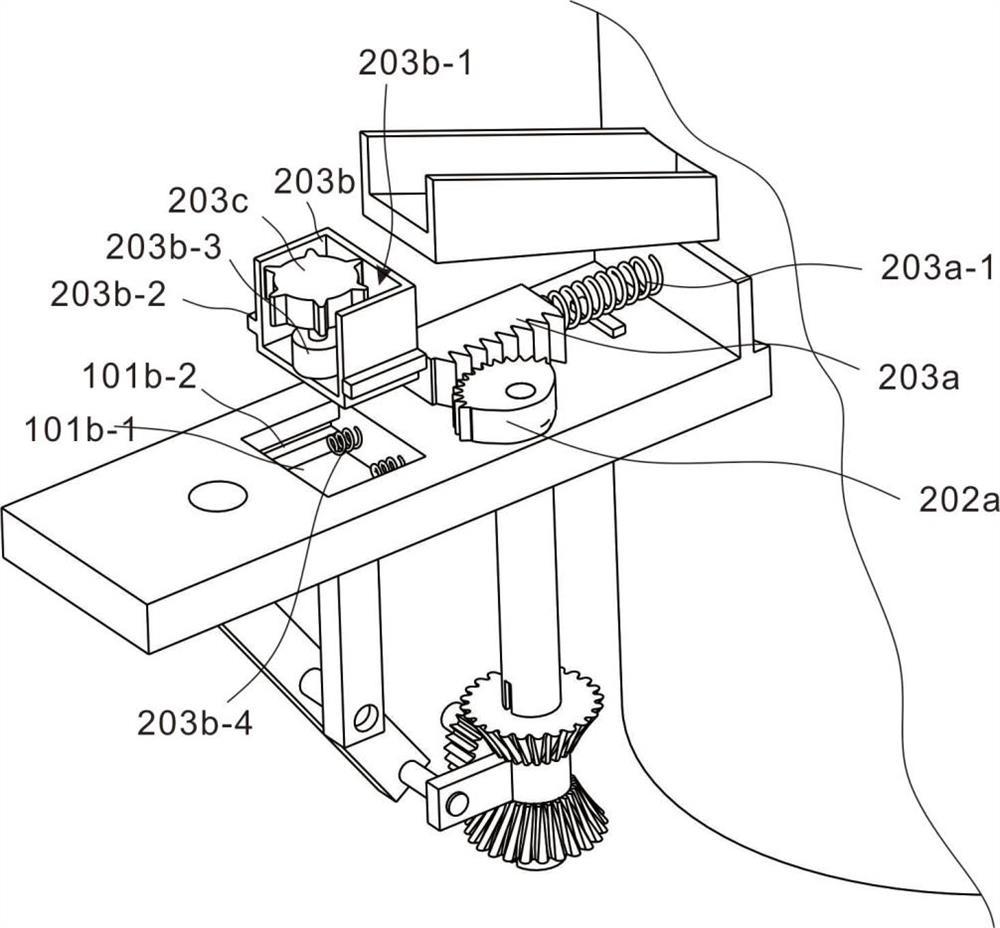
[0030] refer to Figure 2~Figure 4 , which is the second embodiment of the present invention, this embodiment is based on the previous embodiment, the toggle member 203 includes a tooth block 203a, a tooth seat 203b and a second gear 203c, and the tooth seat 203b is movably installed on the mounting plate 101b; the second The gear 203c is located in the gear seat 203b and driven by the second motor 203b-3; the gear block 203a is horizontally installed on the mounting plate 101b to move horizontally.

[0031] The drive assembly 200 also includes a first bevel gear 204 and a second bevel gear 205, the first bevel gear 204 and the second bevel gear 205 are connected through the sleeve A and the first bevel gear 204 and the second bevel gear 205 are connected to the sleeve. A is symmetrically arranged; the motor gear 201 can mesh with the first bevel gear 204 or the second bevel gear 205 respectively. The first bevel gear 204 and the second bevel gear 205 are sleeved on the rotat...


PUM


Abstract

The invention discloses a material mixing device for ceramic clay manufacturing. The material mixing device comprises a material mixing assembly and a driving assembly, the material mixing assembly comprises a melting furnace, a material conveying disc and a steering wheel, a slideway is arranged on the outer wall of the melting furnace, the slideway is connected with the material conveying disc, the steering wheel is installed in the material conveying disc and is rotatably connected with the material conveying disc, an installation plate is arranged on the outer wall of the melting furnace, and a circular shaft is arranged at the bottom of the steering wheel and penetrates through the conveying disc to be connected to the installation plate; and the driving assembly comprises a motor gear, a rotating rod and a shifting piece, the motor gear is in driving connection with the rotating rod, the rotating rod penetrates through the installation plate to be connected with the shifting piece arranged on the installation plate, and the shifting piece is matched with the steering wheel. A periodic timing device is arranged outside a calcining furnace, different materials can periodically fall into the calcining furnace in order, clay is effectively combusted, internal components of the clay are fully combusted, and fired ceramic is more attractive and durable.

Description

technical field [0001] The invention relates to the technical field of clay mixing, in particular to a mixing device for making vitrified clay. Background technique [0002] In the ceramic production process, clay is a must for making ceramics. The quality of clay and the content of internal components are very important. Good ceramics are both beautiful and durable. Therefore, we need to prepare clay with different components and then fire it. When firing clay, it is necessary to control the input of different clay mixtures at different times. Each material cannot be thrown into the combustion furnace at the same time. In order to avoid uneven firing of clay components caused by simultaneous input of mixtures, it is necessary to periodically input mixtures. . Contents of the invention [0003] The technical problem to be solved by the present invention is that when the traditional ceramic clay is fired, it is not easy to control the input time of mixing materials, which ...

Claims


Application Information

Patent Timeline
IPC IPC(8): F27B17/00F27D3/00F27D3/06
CPCF27B17/0041F27D3/0022F27D3/06
Inventor 陈东顺陈浩陈士卫
Owner XINYI XIYI ADVANCED MATERIALS RES INST OF IND TECH CO LTD
Why Eureka
Try Eureka