
An installation method of spot heat flow sensor for aerodynamic thermal test in wind tunnel

A technology of heat flow sensor and aerodynamic heat, applied in aerodynamic tests, instruments, measuring devices, etc., can solve problems such as fluctuations in heat flow distribution, occurrence of shunt vortices, local flow field structure and influence of aerothermal test results, and achieve improved measurement Data accuracy, the effect of reducing installation errors

Active Publication Date: 2021-12-24
中国空气动力研究与发展中心超高速空气动力研究所
View PDF0 Cites 0 Cited by
  • Summary
  • Abstract
  • Description
  • Claims
  • Application Information

AI Technical Summary

Problems solved by technology

When the height of the point-type heat flow sensor is raised / depressed / inclined relative to the surface of the physical test model is small, the disturbance attenuates quickly and will not affect the flow field and test results, but when the point-type heat flow sensor is raised relative to the model surface When the height of / sag / inclination increases to a specific height, the disturbance will be further amplified, and even the phenomenon of split vortex will appear, which will affect the local flow field structure and aerothermal test results
[0005] It is conceivable that the roughness caused by the installation process error of the point-type heat flow sensor has a great influence on the test results, not only will the heat flow distribution fluctuate, but also the measured value of the heat flow at each installation point is consistent with that of the undisturbed case. The actual heat flow value will be quite different

Method used


Image

  • An installation method of spot heat flow sensor for aerodynamic thermal test in wind tunnel
  • An installation method of spot heat flow sensor for aerodynamic thermal test in wind tunnel
  • An installation method of spot heat flow sensor for aerodynamic thermal test in wind tunnel

Examples


Embodiment 1

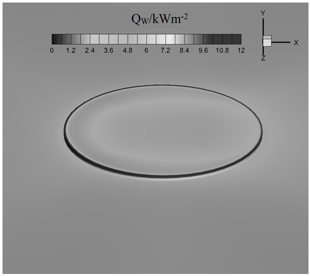
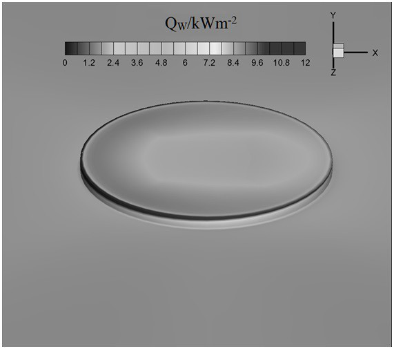
[0053] The physical test model of the present embodiment is a flat plate, and the flow Mach number Ma ∞ =12.0, the flow unit Reynolds number Re ∞ =4.03×10 6 / m, the typical area point is about 0.22m away from the head of the flat model, the diameter is 2mm, the height of the protrusion / depression is 0.05mm and 0.1mm, and the angle of attack is 0°. The obtained local heat flow nephogram is shown in Figure 2a ~ Figure 2d , the obtained aerodynamic heat flow value, aerodynamic heat flow value and h0 value are shown in Table 1.

[0054]

[0055] From Figure 2a ~ Figure 2d It can be seen in the figure that the discontinuity of the plate is caused by the installation of the simulated point heat flow sensor protrusion / depression, so that the local heat flow has a strong discontinuous distribution. It can be seen that there is a significant difference in the B(h) value for different heights of sensor bumps / sags. Taking N=0.05, comparative analysis shows that only when the bum...


PUM


Abstract

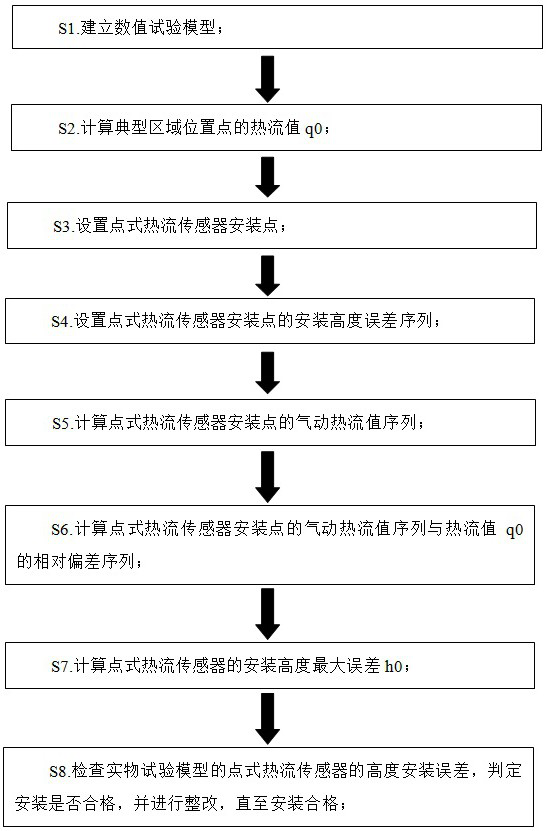
The invention discloses a method for installing a point heat flow sensor used in wind tunnel aerodynamic heat tests. This method establishes a numerical test model; calculates the heat flow value q0 of a typical area location point; sets the point type heat flow sensor installation point; sets the installation height error sequence of the point type heat flow sensor installation point; calculates the aerodynamic heat flow value sequence of the point type heat flow sensor installation point ; Calculate the relative deviation sequence between the aerodynamic heat flow value sequence of the point heat flow sensor installation point and the heat flow value q0; calculate the maximum error h0 of the installation height of the point heat flow sensor; check the height installation error of the point heat flow sensor of the physical test model, and determine the installation Whether it is qualified, and make rectification until the installation is qualified. This method can reduce the installation error of the point heat flow sensor and improve the measurement data accuracy of the wind tunnel aerothermal test.

Description

technical field [0001] The invention belongs to the technical field of ground wind tunnel test, and in particular relates to a method for installing a point heat flow sensor used for wind tunnel aerodynamic heat test. Background technique [0002] Accurate wind tunnel aerothermal test measurement results not only provide support for aircraft thermal protection design, but also verify various theoretical calculation methods, but there are many factors that affect the wind tunnel aerothermal test measurement results, and the installation error of the heat flow sensor is an important influence one of the factors. [0003] Installing a point-type heat flow sensor on the surface of the physical test model will inevitably damage the surface of the physical test model to a certain extent. Moreover, relative to the surface of the physical test model, there is always a difference in the installation height of the point heat flow sensor, so the surface of the physical test model is a...

Claims


Application Information

Patent Timeline
Patent Type & Authority Patents(China)
IPC IPC(8): G01M9/02G01M9/06G06F30/18G06F30/28G06F111/10G06F113/08G06F119/08G06F119/14
CPCG01M9/02G01M9/06G06F30/18G06F30/28G06F2111/10G06F2113/08G06F2119/08G06F2119/14
Inventor 陈挺石义雷赵金山张志刚廖军好粟斯尧肖雨余嘉罗万清王勇
Owner 中国空气动力研究与发展中心超高速空气动力研究所
Learn More