Lighting device and laser projection equipment

A lighting device and light valve technology, applied in the field of laser, can solve the problem of large volume of the lighting device, and achieve the effect of reducing the volume and reducing the volume.

Pending Publication Date: 2021-11-12
QINGDAO HISENSE LASER DISPLAY CO LTD
View PDF0 Cites 2 Cited by
  • Summary
  • Abstract
  • Description
  • Claims
  • Application Information

AI Technical Summary

Problems solved by technology

[0004] The volume of the above-mentioned lighting device is relatively large

Method used


Image

  • Lighting device and laser projection equipment
  • Lighting device and laser projection equipment
  • Lighting device and laser projection equipment

Examples


Embodiment Construction

[0041] In order to make the purpose, technical solution and advantages of the present application clearer, the implementation manners of the present application will be further described in detail below in conjunction with the accompanying drawings.

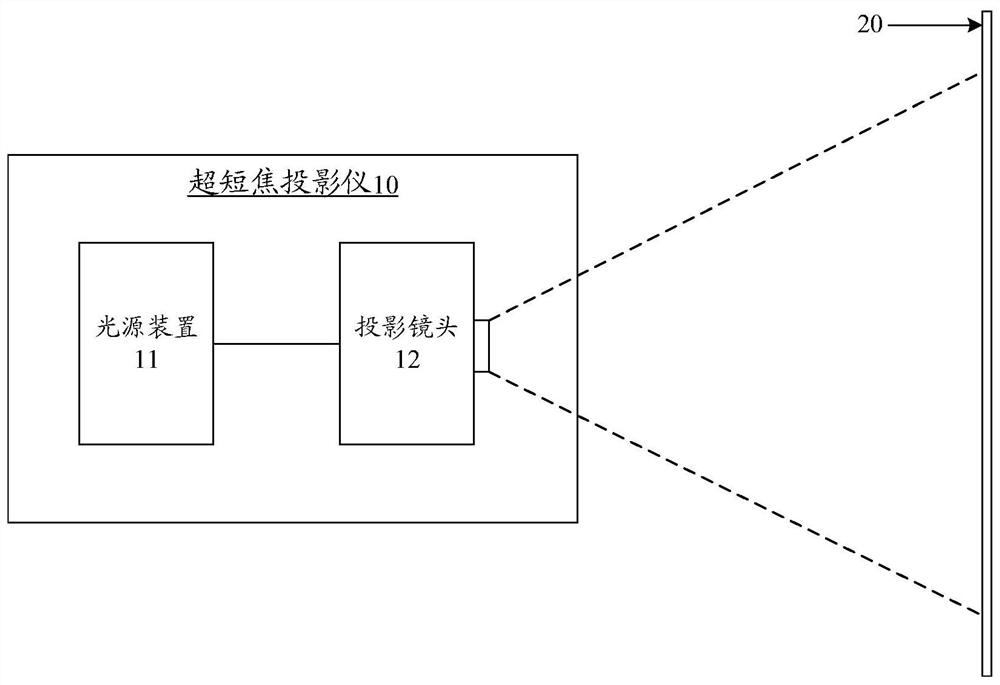
[0042] figure 1 It is a schematic diagram of the implementation environment involved in the embodiment of the present application, and the implementation environment may include an ultra-short-throw projector 10 and a projection screen 20 .

[0043] The laser projector 10 may include an illumination device 11 and a projection lens 12 . The lighting device 11 is used to provide a light source to the projection lens 12 , and the projection lens 12 is used to project a preset pattern onto the projection screen 20 according to the light source provided by the lighting device 11 .

[0044] The projection screen 20 is used to carry the pattern projected by the projection lens 12 . The projection screen 20 may be made of various mater...


PUM


Abstract

The invention discloses a lighting device and laser projection equipment, and belongs to the technical field of laser. A lens assembly, a total internal reflection prism assembly and a light valve are sequentially arranged in the light path direction of the lighting device; the lens assembly comprises a first lens and a second lens which are sequentially arranged in the light path direction, the first lens guides a light beam to the second lens after receiving the light beam, the second lens guides the received light beam to the total internal reflection prism assembly, the light beam is output to the light valve through the total internal reflection prism assembly, and the light valve outputs the received light beam to a camera; and a first included angle is formed between the optical axis of the first lens and the optical axis of the light beam entering the first lens and used for compensating the view field optical path. According to the lighting device, a reflector does not need to be arranged, then the size of the lighting device can be reduced, the problem that the size of a lighting device in the related technology is large is solved, and the effect of reducing the size of the lighting device is achieved.

Description

technical field [0001] The present application relates to the field of laser technology, in particular to an illuminating device and laser projection equipment. Background technique [0002] At present, ultra-short-throw projectors can project large-size images in the case of short-distance projection, and are widely used for their advantages of high space utilization and small size. A light valve (English: digital micromirror device, DMD for short) is a digital micromirror device, which generally uses a short side of the light valve to receive incident light to reduce the size of the lighting device. [0003] An illuminating device in the related art includes a uniform light component, a lens assembly, a plane reflector and a compensating prism. Since the light valve and the light uniform component have a certain included angle, the light path can be better received. Therefore, the light uniform component and the light valve A lens assembly, a plane reflector located in th...

Claims


Application Information

Patent Timeline
Patent Type & Authority Applications(China)
IPC IPC(8): G03B21/20
CPCG03B21/2033G03B21/206G03B21/208
Inventor 杜玉楠陈陆阴亮
Owner QINGDAO HISENSE LASER DISPLAY CO LTD
Why Eureka
Try Eureka