25G optical module OAM modulation circuit

A modulation circuit and optical module technology, which is applied in the field of optical modules, can solve the problems of unable to decode OAM modulated optical signals, screen out OAM modulated signals, and not adjust the modulation current, so as to improve development efficiency, facilitate post-debugging, and low cost Effect

Inactive Publication Date: 2021-11-12
JIANGSU ALLRAY
View PDF5 Cites 0 Cited by
  • Summary
  • Abstract
  • Description
  • Claims
  • Application Information

AI Technical Summary

Problems solved by technology

[0004] The purpose of the present invention is to provide a 25G optical module OAM modulation circuit to solve the problem that the traditional optical module OAM modulation circuit proposed in the above-mentioned background technology needs an independent FPGA for Manchester encoding and decoding, the implementation cost is high, and the modulation current is large It is not adjustable, and can only decode the modulated signal of optical power in a specific interval, which has great limitations, and the receiving end converts the optical signal into an electrical signal through the sampling resistor and directly sends it to the operational amplifier, without filtering the useful OAM modulated signal out, causing the magnification factor to be affected by DC light, and it is impossible to decode OAM modulated optical signals of any size.

Method used


Image

  • 25G optical module OAM modulation circuit

Examples


Embodiment Construction

[0015] The following will clearly and completely describe the technical solutions in the embodiments of the present invention with reference to the accompanying drawings in the embodiments of the present invention. Obviously, the described embodiments are only some, not all, embodiments of the present invention. Based on the embodiments of the present invention, all other embodiments obtained by persons of ordinary skill in the art without making creative efforts belong to the protection scope of the present invention.

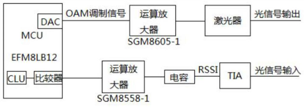
[0016] see figure 1 , a 25G optical module OAM modulation circuit, the modulation method comprising the following steps:

[0017] S1. First, connect the MCU module, operational amplifier, laser, capacitor and TIA together in real time through signal transmission wires, and connect the connection port of the laser and TIA to the signal that needs to be modulated in real time through the signal input terminal and model output terminal. In the circuit, start the...


PUM


Abstract

The invention discloses a 25G optical module OAM modulation circuit, and a modulation method comprises the following steps: S1, firstly, respectively connecting an MCU module, an operational amplifier, a laser, a capacitor and a TIA together in real time through signal transmission wires; connecting the connecting ports of the laser and the TIA into a circuit needing to be modulated in real time through a signal input end and a model output end, starting the MCU, achieving Manchester encoding of OAM modulation signals through programming, converting the OAM modulation signals into analog quantity through D / A of the MCU, and adjusting the analog quantity through software programming; S2, converting the current into current through an operational amplifier, and coupling the current into a laser; wherein after a receiving end converts an optical signal into an electric signal through a sampling resistor, the electric signal is not directly sent to an amplifier, but a direct current component is removed through a blocking capacitor, so that useless direct current signals are removed, and useful OAM modulation signals are amplified; and S3, finally realizing Manchester decoding of the OAM modulation signals through a CLU unit in the MCU.

Description

technical field [0001] The invention relates to the technical field of optical modules, in particular to a 25G optical module OAM modulation circuit. Background technique [0002] In recent years, with the rapid advancement of 5G construction, a large number of 25G optical modules have been used in 5G fronthaul networks. In order to facilitate the management of optical modules and reduce the fault location time, China Mobile and China Telecom require 25G optical modules to add OAM modulation functions. The OAM modulation function is to modulate the digital information containing the state of the optical module into the optical layer signal through Manchester encoding, and demodulate the digital signal from the optical layer signal. [0003] The traditional optical module OAM modulation circuit scheme is that the optical module transmitter end encodes the optical module status information collected by the MCU through the FPGA, converts it into a current coupled to the laser t...

Claims


Application Information

Patent Timeline
Patent Type & Authority Applications(China)
IPC IPC(8): H04B10/2575H04B10/516
CPCH04B10/25752H04B10/5161
Inventor 郭世伟宋怀成于佩
Owner JIANGSU ALLRAY
Why Eureka
Try Eureka