
High temperature superconductor cable

A superconductor and cable technology, applied in the field of high-temperature superconductor cables, can solve problems such as damaged tape

Pending Publication Date: 2021-11-12
TOKAMAK ENERGY
View PDF11 Cites 0 Cited by
  • Summary
  • Abstract
  • Description
  • Claims
  • Application Information

AI Technical Summary

Problems solved by technology

These may damage the strap, reducing the local I c

Method used


Image

  • High temperature superconductor cable
  • High temperature superconductor cable
  • High temperature superconductor cable

Examples


Embodiment Construction

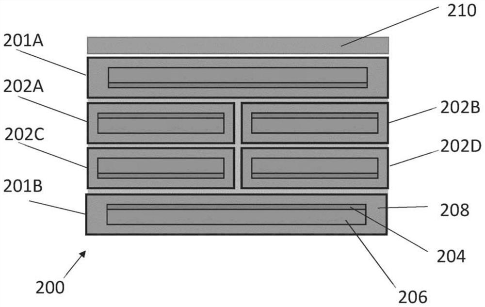
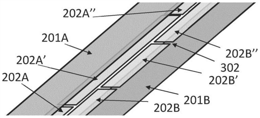
[0046] The present invention relates to an HTS cable comprising stacked HTS ribbons that allows the current distribution across the cable width and between ribbons to be adjusted to produce a more uniform current density. This allows the creation of an HTS magnet in which the current density is more uniformly distributed between the strips and / or in which the HTS magnet is more uniform across each turn. These properties greatly contribute to the design of HTS magnets, as the "real" properties of the magnets, such as the uniformity of the magnetic field, will be more similar to what HTS magnet designers thought.

[0047] The current distribution across the width of the cable can also be adjusted so that it is intentionally non-uniform, with the aim of making the magnetic field angle to the ab plane of the ReBCO layer in each strip as close to zero as possible. This maximizes the critical current of the cable. As described below, the voltage developed across the HTS cable also ...


PUM

PropertyMeasurementUnit
critical temperatureaaaaaaaaaa

Abstract

A cable for carrying electrical current in a coil of a magnet. The magnet comprises an HTS transport tape and a shunt assembly comprising two or more HTS shunt tapes arranged side-by-side across a face of the transport tape. Each of the transport and shunt tapes comprises a substrate layer and an HTS layer of high temperature superconductor (HTS) material, the layers of the shunt tapes extending parallel to the layers of the transport tape.

Description

technical field [0001] The present invention relates to cables for carrying electrical current in magnet coils and comprising high temperature superconducting material. In particular, but not exclusively, the present invention relates to a nuclear fusion reactor comprising a magnetic plasma confinement system comprising a magnetic coil wound with such a cable. Background technique [0002] Superconducting materials are generally divided into "high temperature superconductors (HTS)" and "low temperature superconductors" (LTS). LTS materials such as niobium and NbTi are metals or metal alloys whose superconductivity can be described by BCS theory. All low temperature superconductors have a critical temperature below about 30K (where above this critical temperature, even in a zero magnetic field, the material is electrically incapable of superconducting). The behavior of HTS materials is not described by BCS theory, and such materials may have critical temperatures above abou...

Claims


Application Information

Patent Timeline
Patent Type & Authority Applications(China)
IPC IPC(8): H01F6/06G21B1/05H01B12/06
CPCH01F6/06H01B12/06G21B1/05G21B1/057Y02E30/10Y02E40/60
Inventor 罗伯特·斯莱德
Owner TOKAMAK ENERGY
Learn More