Heating device
A heating device and heating chamber technology, applied in electric heating devices, microwave heating, ohmic resistance heating, etc., can solve the problems of uneven heating and uneven heating of the heating object, and achieve the effect of suppressing uneven heating
- Summary
- Abstract
- Description
- Claims
- Application Information
AI Technical Summary
Problems solved by technology
Method used
Image
Examples
Embodiment approach 1
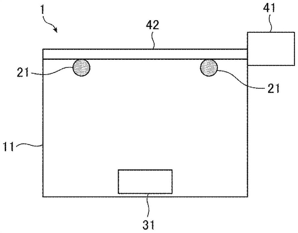
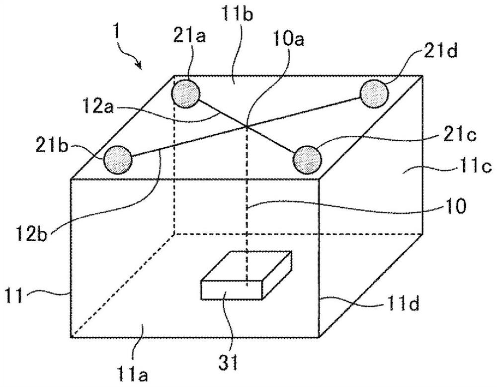
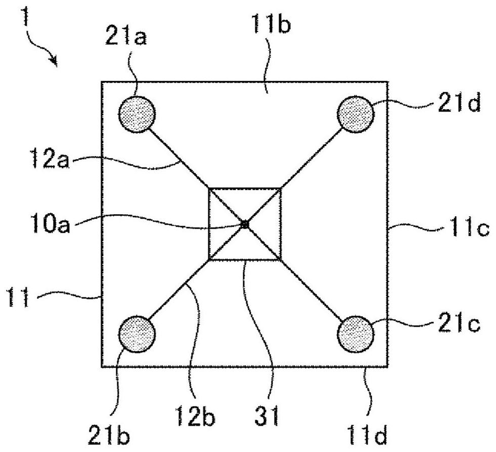
[0044] figure 1 It is a schematic diagram showing a schematic configuration of the heating device 1 according to Embodiment 1, and is described through the wall surface of the heating chamber 11 in order to visually confirm the microwave radiation elements 21 a to 21 d and the heating object 31 located inside the heating chamber 11 . The heating device 1 includes a heating chamber 11 , a plurality of microwave radiation elements 21 , a power generator 41 , and a power distribution circuit 42 . A heating object 31 is housed in the heating chamber 11 . For example, the wall surfaces of the heating chamber 11 other than the wall surface on which the heating chamber door is provided are made of metal shielding plates. In addition, an electromagnetic wave shielding structure is provided on the heating chamber door. Thus, the heating chamber 11 forms an electrically closed space in which microwaves are sealed.
[0045] The power generator 41 is a power generator that generates mi...
Embodiment approach 2
[0127] Figure 18 It is a perspective view which shows the structure of the heating apparatus 1F of Embodiment 2. also, Figure 19 It is a plan view showing the structure of the heating device 1F. exist Figure 18 and Figure 19 In the figure, the microwave radiating elements 21a to 21f and the object to be heated 31 located in the heating chamber 11 are visually recognized, and the description is made through the wall of the heating chamber 11, and descriptions of the power generation device 41 and the power distribution circuit 42 are omitted. The heating device 1F includes six microwave radiation elements (N=3) in the heating chamber 11 .
[0128] The heating chamber 11 has a rectangular parallelepiped shape having a bottom surface 11a, a top surface 11b, and a side surface 11c, and a heating chamber door 11d is provided on one side surface 11c. The side surface other than the heating chamber door 11d is provided as an electromagnetic wave shielding plate, and since th...
Embodiment approach 3
[0142] Figure 20 It is a perspective view which shows the structure of the heating apparatus 1G of Embodiment 3. also, Figure 21 It is a plan view showing the structure of the heating device 1G. exist Figure 20 and Figure 21 In the figure, in order to visually recognize the microwave radiation elements 21a to 21h and the object to be heated 31 located in the heating chamber 11, the description is made through the wall surface of the heating chamber 11, and descriptions of the power generation device 41 and the power distribution circuit 42 are omitted. Moreover, 1 G of heating apparatuses are equipped with 8 microwave radiation elements (N=4) in the heating chamber 11.
[0143] like Figure 20As shown, the heating chamber 11 is in the shape of a cuboid having a bottom surface 11a, a top surface 11b, and a side surface 11c, and a heating chamber door 11d is provided on one side surface 11c. The side surface other than the heating chamber door 11d is provided as an ele...
PUM
 Abstract
Description
Claims
Application Information
 - R&D
- Intellectual Property
- Life Sciences
- Materials
- Tech Scout
- Unparalleled Data Quality
- Higher Quality Content
- 60% Fewer Hallucinations
Browse by: Latest US Patents, China's latest patents, Technical Efficacy Thesaurus, Application Domain, Technology Topic, Popular Technical Reports.
© 2025 PatSnap. All rights reserved.Legal|Privacy policy|Modern Slavery Act Transparency Statement|Sitemap|About US| Contact US: help@patsnap.com


