Heating device

a heating device and heating chamber technology, applied in the field of heating devices, can solve the problems of uneven unfavorable etc., and achieve the effect of suppressing unfavorable heating in the heating of the object to be heated

Pending Publication Date: 2021-12-30
MITSUBISHI ELECTRIC CORP
View PDF0 Cites 0 Cited by
  • Summary
  • Abstract
  • Description
  • Claims
  • Application Information

AI Technical Summary

Benefits of technology

[0009]According to the present invention, a plurality of pairs of microwave radiation elements arranged on at least one plane orthogonal to a reference line set in the heating chamber, the pairs of microwave radiation elements each including two microwave radiation elements facing each other across an intersection point between the reference line and the plane are provided. The microwave power is distributed to a plurality of the microwave radiation elements constituting the plurality of pairs of microwave radiation elements by setting a phase difference of an angle obtained by dividing 360° by the number of a plurality of the microwave radiation elements clockwise or counterclockwise in turn around the reference line. For example, when there are two pairs of microwave radiation elements, a phase difference of 90° is set clockwise or counterclockwise in turn around the reference line, and the microwave powers are distributed to the four microwave radiation elements constituting these pairs. As a result, an electric field mode in which the electric field in the heating chamber rotates in time is obtained. As the electric field mode rotates, a wide range heating distribution is achieved for the object to be heated, so that uneven heating in the object to be heated can be suppressed.

Problems solved by technology

A heating device that heats an object to be heated using an electromagnetic wave has an advantage that the object to be heated can be heated in a short time, but also has a disadvantage that uneven heating occurs in the object to be heated.
For example, in a heating device, since the inside of a heating chamber is an electrically closed space, due to the nature of an electromagnetic wave, a standing wave of a microwave (2.45 GHz) emitted into the heating chamber is generated, so that uneven heating occurs in an object to be heated.

Method used


Image

  • Heating device
  • Heating device
  • Heating device

Examples


first embodiment

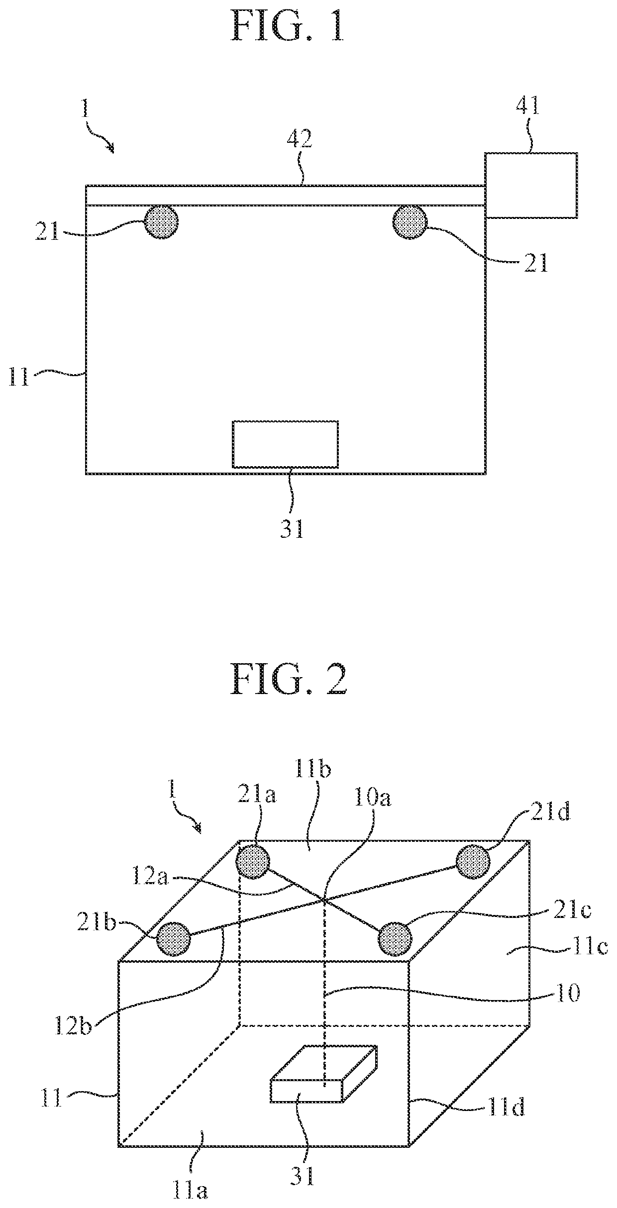
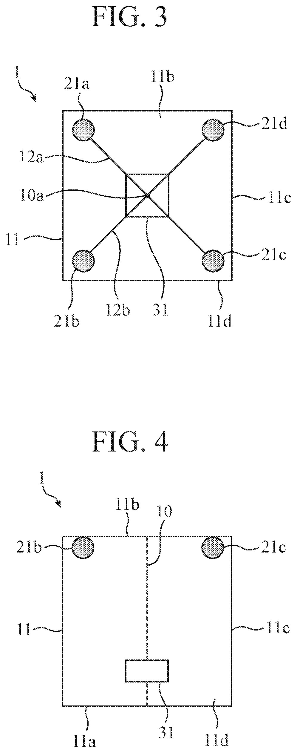
[0039]FIG. 1 is a schematic view illustrating an outline of a configuration of a heating device 1 according to the first embodiment. In order to visually recognize microwave radiation elements 21a to 21d and an object to be heated 31 inside a heating chamber 11, the walls of the heating chamber 11 are drawn to be transparent. The heating device 1 includes a heating chamber 11, a plurality of microwave radiation elements 21, a power generation device 41, and a power distribution circuit 42. The object to be heated 31 is housed in the heating chamber 11. The heating chamber 11 is configured such that, for example, its wall surfaces other than the wall surface on which a heating chamber door is provided is formed of a metal shielding plate. The heating chamber door is provided with an electromagnetic wave shielding structure. Thus, the heating chamber 11 forms an electrically closed space in which microwaves are confined.

[0040]The power generation device 41 is a power generation unit f...

second embodiment

[0121]FIG. 18 is a perspective view illustrating a configuration of a heating device 1F according to the second embodiment. FIG. 19 is a top view illustrating the configuration of the heating device 1F. In FIGS. 18 and 19, in order to visually recognize microwave radiation elements 21a to 21f and an object to be heated 31 in a heating chamber 11, the walls of the heating chamber 11 are drawn to be transparent, and the description of a power generation device 41 and a power distribution circuit 42 is omitted. The heating device 1F includes six microwave radiation elements (N=3) in the heating chamber 11.

[0122]The heating chamber 11 has a rectangular parallelepiped shape having a bottom face 11a, a top face 11b, and side faces 11c, and a heating chamber door 11d is provided on one of the side faces 11c. The faces other than a side face on which the heating chamber door 11d is provided serve as electromagnetic wave shielding plates, and the heating chamber door 11d is provided with an ...

third embodiment

[0135]FIG. 20 is a perspective view illustrating a configuration of a heating device 1G according to the third embodiment. FIG. 21 is a top view illustrating the configuration of the heating device 1G. In FIGS. 20 and 21, in order to visually recognize microwave radiation elements 21a to 21h and an object to be heated 31 in a heating chamber 11, the walls of the heating chamber 11 are drawn to be transparent, and the description of a power generation device 41 and a power distribution circuit 42 is omitted. Further, the heating device 1G includes eight microwave radiation elements (N=4) in the heating chamber 11.

[0136]As shown in FIG. 20, the heating chamber 11 has a rectangular parallelepiped shape having a bottom face 11a, a top face 11b, and side faces 11c, and a heating chamber door 11d is provided on one of the side faces 11c. The faces other than a side face on which the heating chamber door 11d is provided serve as electromagnetic wave shielding plates, and the heating chambe...


PUM

PropertyMeasurementUnit
microwave poweraaaaaaaaaa
phaseaaaaaaaaaa
poweraaaaaaaaaa

Abstract

The microwave power is distributed to microwave radiation elements arranged rotationally symmetrically around a reference line on a plane on a top face side of a heating chamber by advancing a feeding phase with a phase difference of 360°/2N clockwise or counterclockwise in turn.

Description

CROSS REFERENCE TO RELATED APPLICATIONS[0001]This application is a Continuation of PCT International Application No. PCT / JP2019 / 015990, filed on Apr. 12, 2019, which is hereby expressly incorporated by reference into the present application.TECHNICAL FIELD[0002]The present invention relates to a heating device that heats an object to be heated using an electromagnetic wave.BACKGROUND ART[0003]A heating device that heats an object to be heated using an electromagnetic wave has an advantage that the object to be heated can be heated in a short time, but also has a disadvantage that uneven heating occurs in the object to be heated. For example, in a heating device, since the inside of a heating chamber is an electrically closed space, due to the nature of an electromagnetic wave, a standing wave of a microwave (2.45 GHz) emitted into the heating chamber is generated, so that uneven heating occurs in an object to be heated.[0004]As a conventional technique for solving this problem, for ...

Claims


Application Information

Patent Timeline
Patent Type & Authority Applications(United States)
IPC IPC(8): H05B6/68H05B6/66H05B6/72
CPCH05B6/686H05B2206/044H05B6/72H05B6/664H05B6/6482
Inventor ITAKURA, HIROSHIOSHIMA, TAKESHI
Owner MITSUBISHI ELECTRIC CORP
Why Eureka
Try Eureka