Carotid artery blood flow in-vitro control device

A control device and arterial blood technology, applied in the field of medical devices, can solve the problem of inconvenient in vitro operation of carotid artery blood flow control, and achieve the effect of avoiding sudden increase of blood flow and facilitating control

Inactive Publication Date: 2021-11-16
张文生
View PDF0 Cites 0 Cited by
  • Summary
  • Abstract
  • Description
  • Claims
  • Application Information

AI Technical Summary

Problems solved by technology

Existing carotid blood flow control is inconvenient to operate in vitro

Method used


Image

  • Carotid artery blood flow in-vitro control device
  • Carotid artery blood flow in-vitro control device
  • Carotid artery blood flow in-vitro control device

Examples


Embodiment approach

[0085] The outer wall of the driven worm gear 44e is formed with a worm gear concave ring, and the worm gear concave ring rotatably fits with the driving lower hole 42b to limit the axial movement of the driven worm gear 44e.

[0086] Thanks to the above-mentioned improved technical solution, the driven worm gear 44e only has a rotational degree of freedom but not an axial movement degree of freedom.

[0087] As a further implementation:

[0088] The driven gear 44a is rotatably disposed on the driven gear shaft, and the driven gear shaft is fixedly disposed on the upper surface of the housing body 42a.

[0089] The lower end of the driven gear shaft is expanded to form a cylindrical gear shaft end, and the inner wall of the driven gear 44a is provided with a gear shaft chamber matching with the gear shaft end.

[0090] Thanks to the above-mentioned improved technical solution, the driven gear 44a only has the degree of freedom of rotation and does not have the degree of free...

Embodiment 1

[0100] Example 1, quick adjustment:

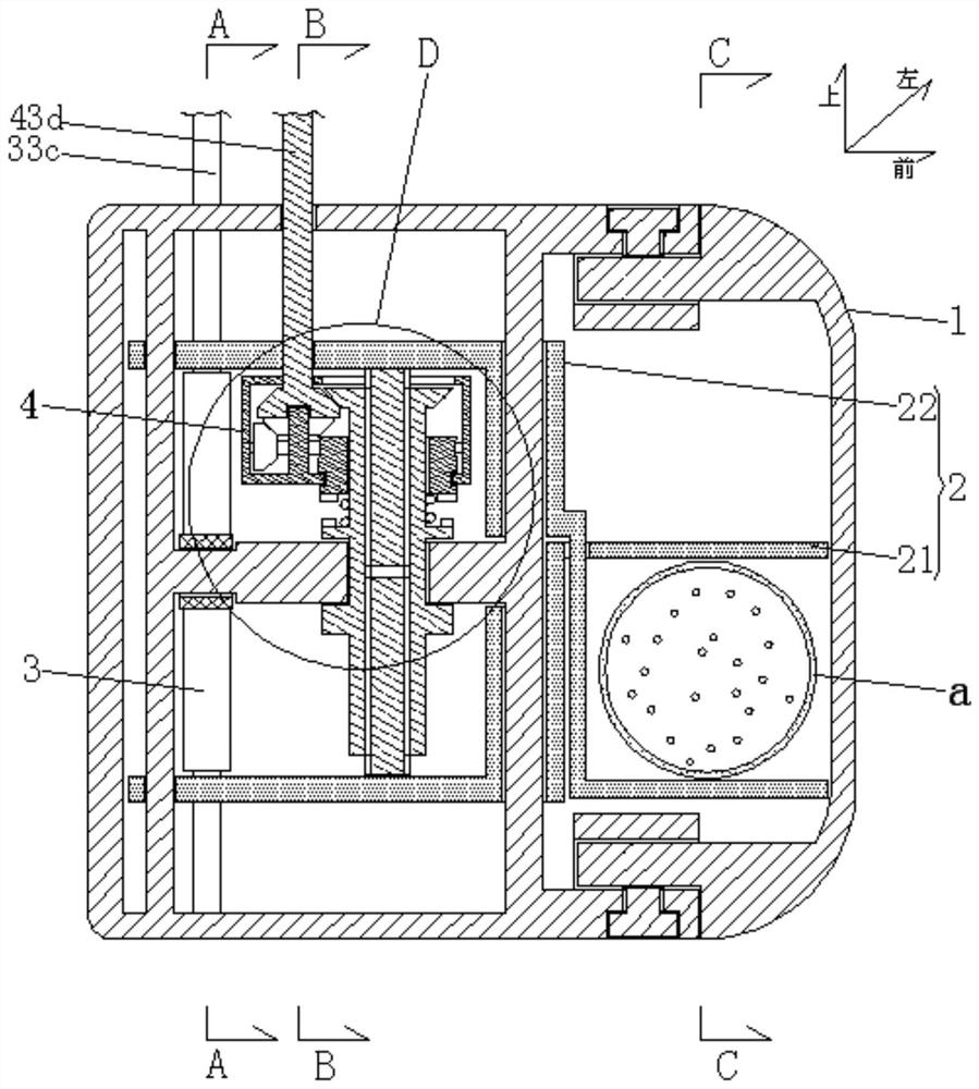
[0101] Pull up the quick adjustment pull rod 33c and the upward rack 33b;

[0102] The upward-moving rack 33b drives the upward-moving push plate 22b, the upward-moving sliding sleeve 22a, the lower insertion plate 22d, and the upward-moving splint 22e to move upward;

[0103] The up-going rack 33b drives the down-going rack 32b to go down through the central gear 31;

[0104] The down-moving rack 32b drives the down-moving push plate 21b, down-moving sliding sleeve 21a, down-moving front plate 21d, and down-moving splint 21e to go down;

[0105] The up-moving splint 22e and the down-moving splint 21e quickly clamp the carotid artery, limit the blood flow of the carotid artery a, and avoid excessive blood perfusion;

Embodiment 2

[0106] Example 2, precise adjustment:


PUM


Abstract

The invention discloses a carotid artery blood flow in-vitro control device which comprises a device shell, the device shell is formed to be in a left-right through hollow shell shape, and the front end of the device shell is open and detachably provided with a front stop plate; a clamping device which is used for clamping the carotid artery of the patient; a quick adjusting device which is used for quickly adjusting the posture of the clamping device; and a fine adjustment device which is used for accurately adjusting the posture of the clamping device. A front sliding plate is longitudinally arranged on the front half portion of an inner cavity of the device shell, a rear sliding plate is longitudinally arranged on the rear half portion of the inner cavity of the device shell, a rear connecting plate is backwards formed in the middle of the rear end face of the front sliding plate, a gear mandrel is formed at the rear end of the rear connecting plate, and the gear mandrel is perpendicularly connected with the rear sliding plate. The clamping device comprises a downward moving clamp and an upward moving clamp; the quick adjusting device comprises a central gear, a push-down assembly and a push-up assembly; the fine adjustment device comprises a lead screw assembly, a transmission shell, a bevel gear driving mechanism and a worm gear driving mechanism.

Description

technical field [0001] The present application relates to the technical field of medical devices, in particular to an external control device for carotid artery blood flow. Background technique [0002] Intracranial blood flow is mainly supplied by four main vessels, the carotid artery and the vertebral artery. With the improvement of people's living standards and the growth of age, there are more and more carotid artery plaques, leading to a linear increase in the incidence of carotid artery plaque stenosis stroke, and the effective method for the treatment of carotid artery stenosis is carotid endarterectomy The overperfusion of cerebral blood flow after operation is the main factor that leads to the life-threatening of patients. Effective control of the blood flow of the blood vessels after opening can obviously avoid the occurrence of overperfusion, thereby saving the life of the patient and improving the prognosis. Existing carotid blood flow control is inconvenient to...

Claims


Application Information

Patent Timeline
Patent Type & Authority Applications(China)
IPC IPC(8): A61B17/122A61B17/128
CPCA61B17/122A61B17/128A61B2017/12004
Inventor 张文生
Owner 张文生
Why Eureka
Try Eureka