Magnetic type welding trolley

A welding trolley and magnetic suction technology, which is applied in welding equipment, auxiliary welding equipment, welding/cutting auxiliary equipment, etc., can solve the problems of welding trolley easy to pull, safety hazards, etc., to improve welding quality, avoid pulleys, and reduce consumption Effect

Pending Publication Date: 2021-11-16
CHENGDU F&M TECH
View PDF0 Cites 3 Cited by
  • Summary
  • Abstract
  • Description
  • Claims
  • Application Information

AI Technical Summary

Problems solved by technology

[0006] The purpose of the present invention is: for the welding trolley of the prior art, the transmission of the pulley and the gear is usually driven by the driving motor to realize its walking on the track. When the driving motor is powered off, there is a problem that the welding trolley is easy to pull, which is easy to cause safety hazards , providing a magnetic welding trolley

Method used


Image

  • Magnetic type welding trolley
  • Magnetic type welding trolley
  • Magnetic type welding trolley

Examples


Embodiment 1

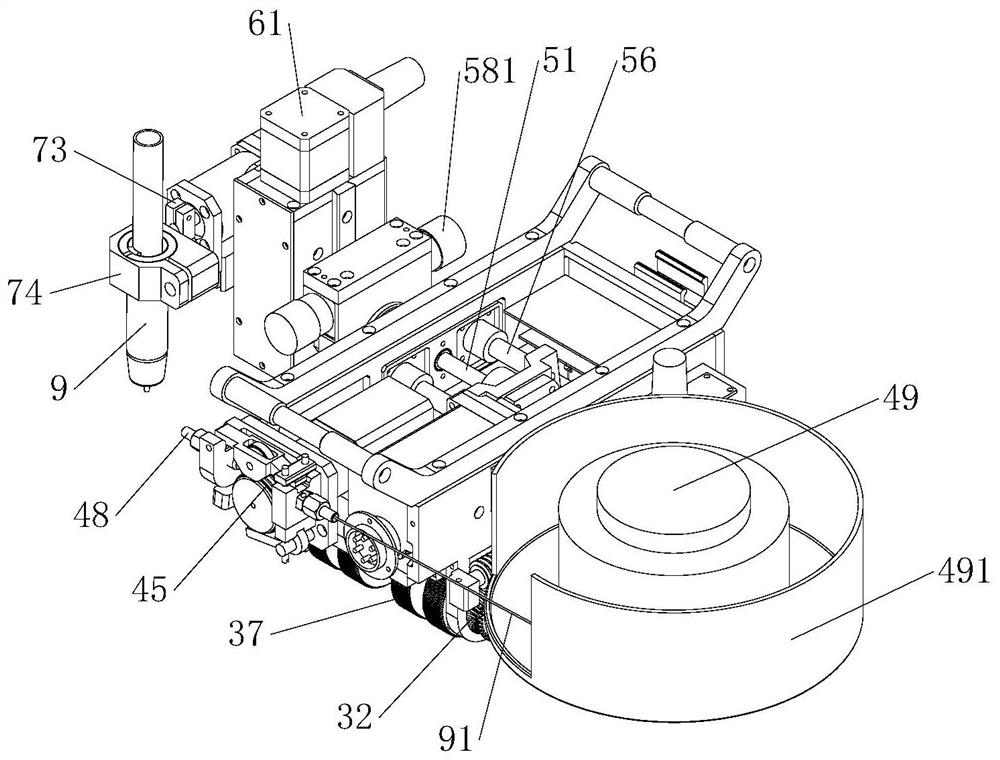
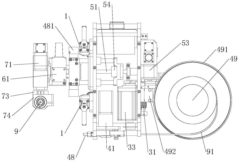
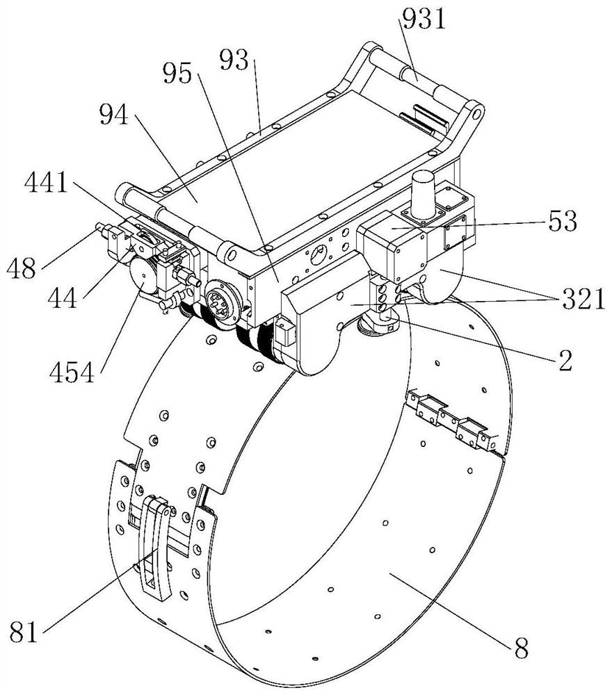
[0094] This embodiment provides a magnetic suction welding trolley, see Figure 1-6 , including trolley body, wire feeding system and welding torch position adjustment system;

[0095] The trolley body is provided with a drive system, and the drive system includes a pulley 34;

[0096] The bottom of the trolley body is provided with a magnetic wheel 37;

[0097] The drive system also includes a drive worm 31 and several drive worm gears 32, the drive worm 31 is arranged along the length direction of the trolley body, the pulley 34 is sleeved on the drive worm 31, and the drive worm 31 engages with all The driving worm gear 32 is fixedly connected to the corresponding magnetic wheel 37 .

[0098] Both the wire feeding system and the position adjustment system of the welding torch of the magnetic suction type welding trolley can adopt existing structures. The drive system uses a drive motor 33 to provide power, such as a stepper motor, which communicates with the circuit driv...


PUM


Abstract

The invention provides a magnetic type welding trolley. The magnetic type welding trolley comprises a trolley body, wherein magnetic wheels are arranged at the bottom of the trolley body; the trolley body is provided with a driving system; the driving system comprises a belt wheel, a driving worm and driving worm wheels; the driving worm is arranged along the length direction of the trolley body; the belt wheel sleeves the driving worm; the driving worm is engaged with all the driving worm wheels; and the driving worm wheels are fixedly connected with the corresponding magnetic wheels. According to the magnetic type welding trolley provided by the invention, all the driving worm wheels are driven by the same driving worm, so that the rotary frequencies of all the driving worm wheels are the same, the walking stability of the welding trolley is facilitated and an inner transmission structure of the welding trolley is easy to reduce. The rotation of the magnetic wheels needs to be driven by the worm wheels and the worm; and after the welding trolley is powered off, the worm wheels and the worm can ensure that the magnetic wheels do not rotate through self-locking, so that a phenomenon that the trolley is slipped after being powered off in a welding process is avoided and the utilization safety of the welding trolley is improved.

Description

technical field [0001] The invention relates to the technical field of pipeline welding trolley, in particular to a magnetic suction welding trolley. Background technique [0002] The welding trolley is the driving mechanism to realize the automatic welding process of the pipeline. It is installed on the welding guide rail and moves along the pipe wall with the welding torch. Existing magnetic suction welding trolleys usually include a bottom plate, side panels, front baffles, rear baffles and a top plate, and the bottom plate, side panels, front baffles, rear baffles and top plates are used to form the welding trolley shape and install other components, Such as installation of driving device, welding torch position adjustment system and wire feeding system, etc., and there are several magnetic wheels at the bottom of the magnetic suction welding trolley. Generally, the magnetic wheels are arranged in a row at the front and back, and all the magnetic wheels in the front row ...

Claims


Application Information

Patent Timeline
Patent Type & Authority Applications(China)
IPC IPC(8): B23K37/02B23K37/00B23K101/06
CPCB23K37/0211B23K37/0252B23K37/0294B23K37/00B23K2101/06
Inventor 陈果田马云军刘华伟李少奎王飞跃
Owner CHENGDU F&M TECH
Why Eureka
Try Eureka