Mechanical structure of automatic clamping device for mechanical polishing

A clamping device and mechanical polishing technology, which is applied to surface polished machine tools, grinding drive devices, and parts of grinding machine tools, etc., can solve problems such as workpiece deformation, affecting work efficiency, and uneven force on the workpiece, achieving guaranteed Position accuracy, reduce labor intensity, uniform force effect

Pending Publication Date: 2021-11-16
HOHAI UNIV
View PDF9 Cites 0 Cited by
  • Summary
  • Abstract
  • Description
  • Claims
  • Application Information

AI Technical Summary

Problems solved by technology

[0002] At present, in the polishing process, mechanical clamping devices are often used. The main function is to fix the workpiece to be processed. The existing mechanical clamping device needs to place the workpiece in the device, and then manually screw the bolt to fix the workpiece. Fixed, due to manual adjustment, it is impossible to accurately judge the clamping process, which also increases the labor intensity of workers, and manual manual adjustment may easily lead to uneven force on the workpiece, resulting in deformation of the workpiece, and the deformed parts do not meet half Finishing and finishing requirements require secondary clamping and trimming of parts, which greatly affects work efficiency

Method used


Image

  • Mechanical structure of automatic clamping device for mechanical polishing
  • Mechanical structure of automatic clamping device for mechanical polishing
  • Mechanical structure of automatic clamping device for mechanical polishing

Examples


Embodiment 1

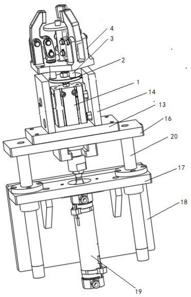
[0034] like figure 1As shown, a mechanical structure of an automatic clamping device for mechanical polishing, including a base, a motor 1, a motor frame, a turntable 2 and a pressing device, the motor 1 is fixed on the side plate 14 and the connecting plate 15 of the motor frame, and the motor The output shaft of 1 is perpendicular to the base, the motor frame is fixed on the base, the turntable 2 is installed on the output shaft of motor 1, and the pressing device is installed on the turntable 2;

[0035] like Figure 5 As shown, the base includes a first support plate 16, a second support plate 17, a riser 18, a second hydraulic cylinder 19 and a slide bar 20, the second support plate 17 is located below the first support plate 16, and the riser 18 is connected to One side of the second support plate 17, the vertical plate 18 is provided with mounting holes for fixing the base; the slide bar 20 is two, and one end of the slide bar 20 is connected on the first support plate...

Embodiment 2

[0043] Based on a method for using a mechanical structure of an automatic clamping device for mechanical polishing, the method includes the following steps:

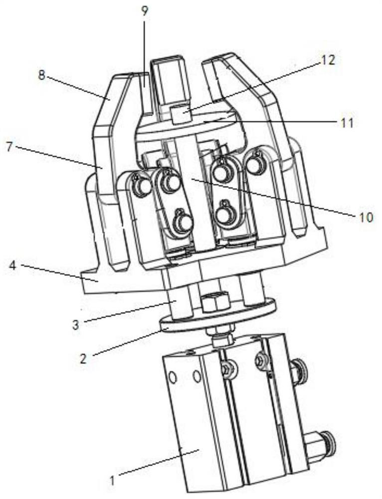
[0044] Step 1. First place the workpiece to be polished on the pallet 11 of the bracket, and align the hollow part of the workpiece to be polished with the limit position

[0045] Column 12;

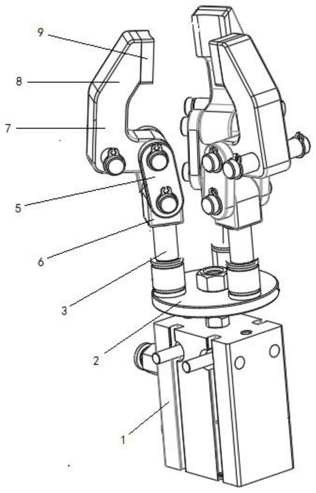
[0046] Step 2, then the infrared sensor on the pallet 11 senses the presence of the workpiece, and transmits the monitored data to the controller of the first hydraulic cylinder 3, and the controller of the first hydraulic cylinder 3 issues an instruction to start the first hydraulic cylinder 3 , so that the first piston rod moves down, and drives the connecting block 6, the connecting piece 5 and the clamping arm, so that the clamping block 6 on the clamping arm is close to each other, and the workpiece is clamped, and the pressure sensor collects the pressing force on the clamping arm in real time block 6 of the pressure data, a...


PUM


Abstract

The invention discloses a mechanical structure of an automatic clamping device for mechanical polishing. The mechanical structure comprises a base, a motor, a rotating disc and a pressing device, the motor is installed on the base, the rotating disc is installed on an output shaft of the motor, and the pressing device is installed on the rotating disc; the pressing device comprises first hydraulic cylinders, clamping arms and supporting pieces, and the number of the first hydraulic cylinders is equal to that of the clamping arms; the fixed end of each first hydraulic cylinder is fixedly connected to the rotating disc, the movable end of each first hydraulic cylinder is fixedly connected with the lower bottom face of the corresponding supporting piece, the telescopic end of a first piston rod of each first hydraulic cylinder penetrates through the corresponding supporting piece and is rotationally connected with the corresponding clamping arm through a first rotating shaft, and the clamping arms are rotationally connected with the supporting pieces through second rotating shafts. and when the first piston rods move downwards, the clamping arms rotationally connected with the first piston rods are driven, the clamping arms rotate around the second rotating shafts, and the ends, clamping workpieces, of the multiple clamping arms are gathered towards the center line side of the output shaft of the motor. Due to the fact that the structure is high in automation degree, the personal working efficiency is improved.

Description

technical field [0001] The invention belongs to the field of mechanical polishing equipment, and in particular relates to a mechanical structure of an automatic clamping device for mechanical polishing. Background technique [0002] At present, in the polishing process, mechanical clamping devices are often used. The main function is to fix the workpiece to be processed. The existing mechanical clamping device needs to place the workpiece in the device, and then manually screw the bolt to fix the workpiece. Fixed, due to manual adjustment, it is impossible to accurately judge the clamping process, which also increases the labor intensity of workers, and manual manual adjustment may easily lead to uneven force on the workpiece, resulting in deformation of the workpiece, and the deformed parts do not meet half Finishing and finishing requirements require secondary clamping and trimming of parts, which greatly affects work efficiency. Contents of the invention [0003] The o...

Claims


Application Information

Patent Timeline
Patent Type & Authority Applications(China)
IPC IPC(8): B24B29/02B24B41/06B24B47/22B24B49/00B24B49/12
CPCB24B29/02B24B41/06B24B47/22B24B49/12B24B49/00
Inventor 刘志豪陈曌文
Owner HOHAI UNIV
Why Eureka
Try Eureka