3D printing device and printing method for embedded circuit products

A 3D printing and product technology, applied in the field of 3D printing, can solve the problems of inconsistent shrinkage rate, trapped air and weak welding, low overall strength, etc., and achieve the effect of not easy to open or short circuit, increase the conductive area, and high reliability of the conductive

Inactive Publication Date: 2021-11-16
恒新增材制造研究中心(佛山)有限公司
View PDF2 Cites 2 Cited by
  • Summary
  • Abstract
  • Description
  • Claims
  • Application Information

AI Technical Summary

Problems solved by technology

When printing layers of different materials are piled up, due to the different materials between layers, the melting temperature is different and the shrinkage rate is inconsistent. Integral, or partial delamination is particularly prone to occur, resulting in low overall strength of the product
Therefore, at present, FDM generally only prints products or parts of a single material
[0004] When the product composition contains different materials, such as embedded circuits in the product, take the production of wearable electronic helmets by FDM as an example. At present, the helmet body is usually printed separately by FDM, and then the parts are assembled with electronic components, or in The installation position is reserved when printing the helmet body, and electronic components are embedded in the installation position later. The production process of wearable electronic helmet products produced by these two methods is cumbersome, and the electronic components inside are easily affected by the external environment, and are prone to short circuits and other situations; There are also processing flow channels set up when printing the helmet body, and circuit conduction is realized by injecting conductive paste into the processing flow channel. Processing the cross-sectional area of ​​the flow channel will greatly increase the cost of the conductive paste

Method used


Image

  • 3D printing device and printing method for embedded circuit products
  • 3D printing device and printing method for embedded circuit products

Examples


Embodiment Construction

[0038] In order to make the object, technical solution and advantages of the present invention clearer, the present invention will be further described in detail below in conjunction with the accompanying drawings.

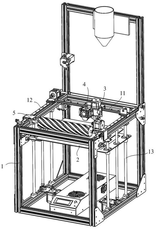
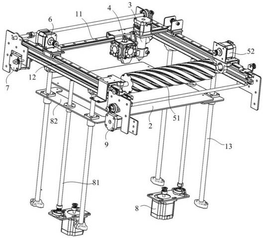
[0039] Such as figure 1 and figure 2As shown, this embodiment provides an embodiment of a 3D printing device with embedded circuit products, including a frame 1, a printing platform 2, a first printing mechanism 3, a second printing mechanism 4 and a milling and flattening module 5. The frame 1 is provided with an X-axis guide rail 11, a Y-axis guide rail 12, and a Z-axis guide rail 13, as well as a first drive mechanism 6, a second drive mechanism 7, a third drive mechanism 8, and a fourth drive mechanism 9. The printing The platform 2 is arranged below the X-axis guide rail 11 and the Y-axis guide rail 12, and is arranged parallel to the X-axis guide rail 11 and the Y-axis guide rail 12; the first driving mechanism 6 is connected to the first printing mechanis...


PUM


Abstract

The invention belongs to the technical field of 3D printing, and discloses a 3D printing device for embedded circuit products. The 3D printing device comprises a rack, a printing platform, a first printing mechanism, a second printing mechanism and a milling module, the rack is provided with an X-axis guide rail, a Y-axis guide rail, a Z-axis guide rail, a first driving mechanism, a second driving mechanism, a third driving mechanism and a fourth driving mechanism; the first driving mechanism is used for driving the first printing mechanism and the second printing mechanism to slide along the X-axis guide rail; the second driving mechanism is used for driving the X-axis guide rail to slide along the Y-axis guide rail; the third driving mechanism is used for driving the printing platform to ascend and descend along the Z-axis guide rail; and the fourth driving mechanism is used for driving the milling module to slide along the Y-axis guide rail. The printing method of the embedded circuit products can be used for printing combination of different materials, the combination effect is good, and the conductive reliability is high.

Description

technical field [0001] The invention relates to the technical field of 3D printing, in particular to a 3D printing device and a printing method for embedded circuit products. Background technique [0002] As a representative of 3D printing technology, Fused Deposition Modeling (Fused Deposition Modeling, FDM) is a process of forming a 3D solid model by superimposing and stacking molten filaments. It mainly extrudes linear filaments through high-temperature nozzles, and then melts them Layers of material are built up to create three-dimensional objects. [0003] For products printed by FDM, the connection between layers is only through the bonding of molten materials. Whether the bonding force between the materials of each layer is balanced directly affects the overall strength of the product. When printing layers of different materials are piled up, due to the different materials between layers, the melting temperature is different and the shrinkage rate is inconsistent. O...

Claims


Application Information

Patent Timeline
Patent Type & Authority Applications(China)
IPC IPC(8): B29C64/118B29C64/20B29C64/232B29C64/236B33Y30/00B29L31/34
CPCB29C64/118B29C64/20B29C64/232B29C64/236B33Y30/00B29L2031/34
Inventor 王晖陈超
Owner 恒新增材制造研究中心(佛山)有限公司
Why Eureka
Try Eureka