
Adjustable composite stabilizer bar and assembling method thereof

A stabilizer bar, adjustable technology, applied in transportation and packaging, manufacturing tools, metal processing, etc., can solve the problems of product cost reduction, complicated assembly process, complex structure, etc., to reduce production and use costs, and realize mass processing production , the effect of reasonable structural design

Active Publication Date: 2021-11-16
ANQING HUITONG AUTOMOTIVE PARTS
View PDF6 Cites 0 Cited by
  • Summary
  • Abstract
  • Description
  • Claims
  • Application Information

AI Technical Summary

Problems solved by technology

Its structure is complicated, the number of parts is large, the weight is large, the fasteners assembled are many, the assembly process is complicated, time-consuming and laborious, the production efficiency is low, the cost is high, and the after-sales cost is high.
[0003] In view of the above-mentioned defects, along with the improvement of technology, although the structure of the thrust bar and the stabilizer bar has also been adopted to form a composite stabilizer bar in the prior art , but in the existing structure, the torsion bar and the leaf springs at both ends are connected as a whole through welding. Although it can meet the requirements of use, it has relatively high requirements for welding technology, and in the process of processing and production, due to the The specifications of the stabilizer bars are different for different models, which requires that each model corresponds to a product, which has poor versatility, and its production, testing, and process standards are not the same, which is not conducive to mass production and processing. The cost of the product is reduced, and with use, if it is deformed during use, it cannot be replaced separately, thereby increasing the cost of use

Method used


Image

  • Adjustable composite stabilizer bar and assembling method thereof
  • Adjustable composite stabilizer bar and assembling method thereof
  • Adjustable composite stabilizer bar and assembling method thereof

Examples


Embodiment Construction

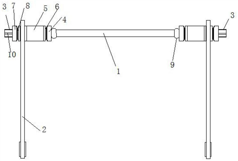
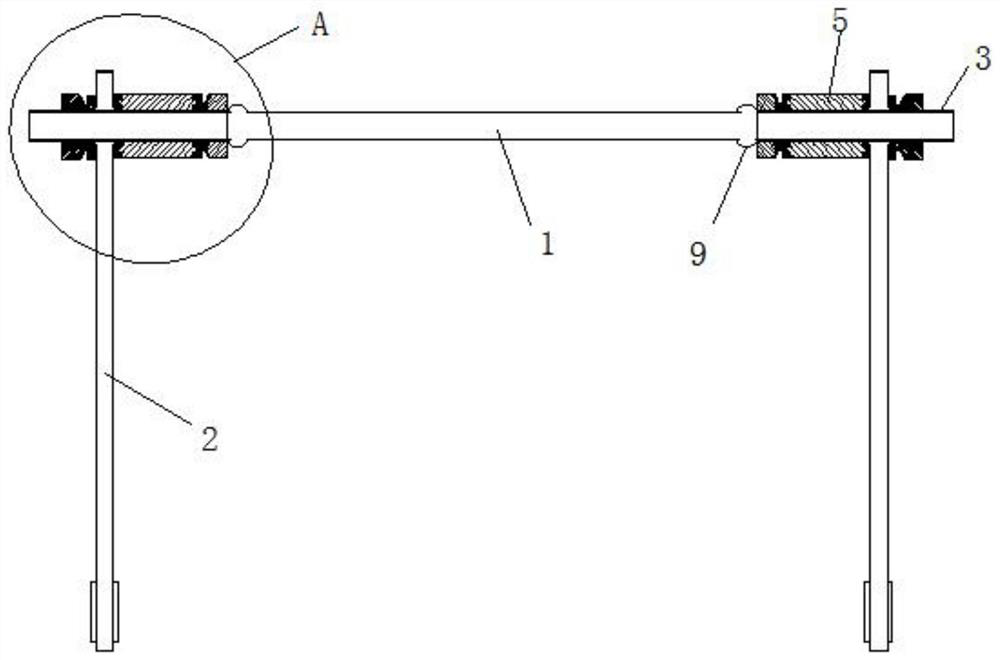
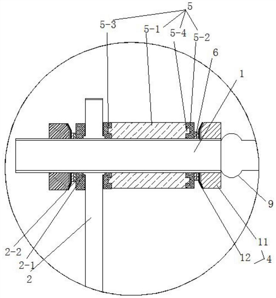
[0033] See attached picture.

[0034]An adjustable composite stabilizer bar, comprising a hollow torsion bar body 1, leaf springs 2 with adjustable center distances are respectively installed at both ends of the torsion bar body 1, and two sections of threads are respectively provided at both ends of the torsion bar body 1 Section 3, the leaf spring 2 is set on the threaded section 3, and the inner side of the leaf spring 2 is limited and fixed by the inner end fixing component. The inner end fixing component includes a fixing component 4 and an adjusting component 5. The fixing component 4 and adjusting An anti-loosening reinforcing component 6 is also installed between the components 5. The fixing component 4 and the adjusting component 5 are both screwed and fixed on the threaded section 3 of the torsion bar body 1, and the outer side of the leaf spring 2 is locked by the outer end. Components are locked and fixed, and the locking component includes a fixed component 2 7, a...


PUM


Abstract

The invention discloses an adjustable composite stabilizer bar and an assembling method thereof. The adjustable composite stabilizer bar comprises a hollow torsion bar body, the two ends of the torsion bar body are each provided with a leaf spring with the adjustable center distance, the two ends of the torsion bar body are each provided with two threaded sections, the threaded sections are sleeved with the leaf springs, and the inner sides of the leaf springs are limited and fixed through inner end fixing assemblies. each inner end fixing assembly comprises a first fixing assembly and an adjusting assembly, a first anti-loosening reinforcing assembly is further installed between the first fixing assembly and the adjusting assembly, the first fixing assembly and the adjusting assembly are both fixed to the threaded section of the torsion bar body in a screwed mode, and the outer side of each leaf spring is locked and fixed through the locking assembly at the outer end; and the locking assembly comprises a second fixing assembly, a second reinforcing assembly is additionally arranged in the second fixing assembly, and the second fixing assembly is also screwed and fixed to the threaded section of the torsion bar body. The structure of a traditional integrated composite stabilizer bar is changed, universality is high, the requirement for batch machining and production can be met, and the production and use cost is reduced.

Description

Technical field: [0001] The invention relates to the field of production and processing of a composite stabilizer bar, and mainly relates to an adjustable composite stabilizer bar and an assembly method thereof. Background technique: [0002] Both the stabilizer bar and the thrust bar are key auxiliary components in the suspension system. The main function of the thrust bar is to prevent the body from excessive lateral roll when turning, causing unnecessary traffic accidents. The stabilizer bar prevents the car from laterally tilting. turn and improve ride comfort. The stabilizer bar is a torsion bar spring made of spring steel, which is shaped like a "U" and runs across the front and rear of the car. The middle part of the rod body is hinged with the frame by a sleeve, and the two ends of the rod are respectively fixed on the left and right hanging lower brackets or shock absorber struts. When the vehicle is running, the longitudinal thrust rod bears the longitudinal force...

Claims


Application Information

Patent Timeline
Patent Type & Authority Applications(China)
IPC IPC(8): B60G21/055B23P19/04
CPCB60G21/0553B23P19/048B23P19/04B23P2700/14
Inventor 徐天石
Owner ANQING HUITONG AUTOMOTIVE PARTS
Learn More