A wind blade conveyor with electronically controlled hydraulic adjustment mechanism

An electronically controlled hydraulic and wind blade technology, which is applied in the direction of mechanical conveyors, conveyors, conveyor objects, etc., can solve the problems of high installation position requirements for conveying equipment, low stability of wind blades, and surface wear of wind blades. The effects of maintaining transmission efficiency, improving surface adhesion, and reducing requirements for the installation environment

Active Publication Date: 2021-12-21
南通艾郎风电科技发展有限公司
View PDF5 Cites 0 Cited by
  • Summary
  • Abstract
  • Description
  • Claims
  • Application Information

AI Technical Summary

Problems solved by technology

[0006] The technical problem to be solved by the present invention is: the stability of the wind blades is not high during the transportation process, and the lifting method is often used for transportation, which not only has low safety, but also easily causes wear on the surface of the wind blades, and at the same time, wind blades of different specifications need to be used together Different types of conveying brackets have high requirements for the installation position of the conveying equipment and have great limitations

Method used


Image

  • A wind blade conveyor with electronically controlled hydraulic adjustment mechanism
  • A wind blade conveyor with electronically controlled hydraulic adjustment mechanism
  • A wind blade conveyor with electronically controlled hydraulic adjustment mechanism

Examples


Embodiment Construction

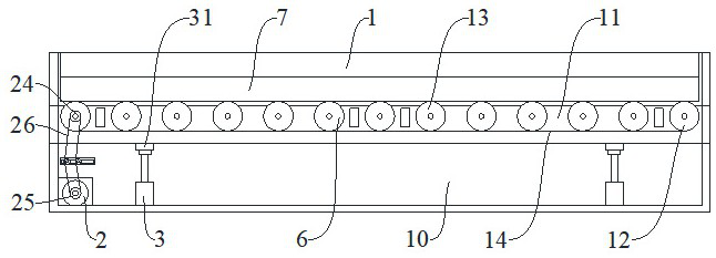
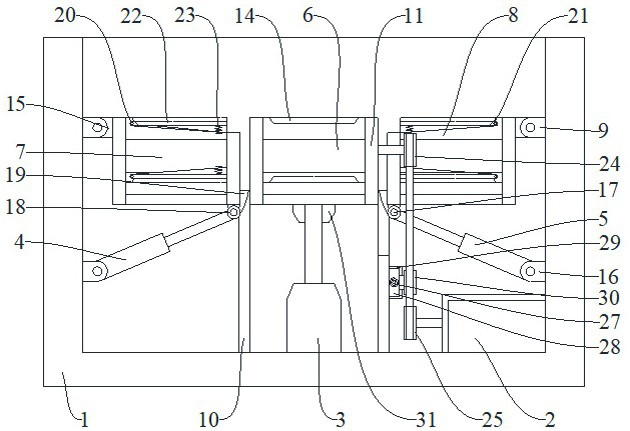
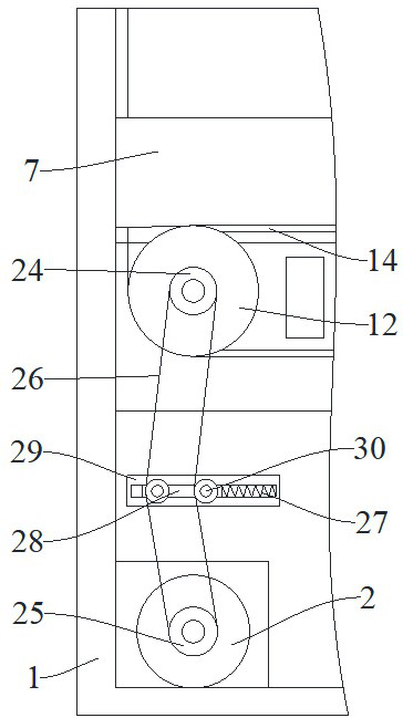
[0027] The present invention is described in further detail now in conjunction with accompanying drawing. These drawings are all simplified schematic diagrams, which only illustrate the basic structure of the present invention in a schematic manner, so they only show the configurations related to the present invention.

[0028] figure 1 , figure 2 , image 3 Figure 4 A wind blade conveyor with an electronically controlled hydraulic adjustment mechanism is shown, including a main support 1, a drive motor 2, a first electronically controlled hydraulic strut 3, a second electronically controlled hydraulic strut 4 and a third electronically controlled hydraulic strut Rod 5, the main support 1 is provided with the middle belt conveying mechanism 6 controlled by the first electronically controlled hydraulic strut 3, the first belt conveying mechanism 7 controlled by the second electrically controlled hydraulic strut 4, and the third electric controlled hydraulic strut 4. The h...


PUM


Abstract

The invention relates to the technical field of wind blade conveying, in particular to a wind blade conveyor with an electronically controlled hydraulic adjustment mechanism, which includes a main support, a driving motor and a hydraulic and electronically controlled strut. A wind blade conveyor with an electronically controlled hydraulic adjustment mechanism of the present invention uses the ground conveying method to convey the wind blades, without the need for high-altitude erection hangers, greatly reducing the requirements for the installation environment, and being applicable to a wider range of environments; The belt conveying mechanism is used for bottom support and translational conveying of the wind blades, and the angle of the surface support can be automatically adjusted according to the surface structure of the wind blades, so that the fit between the conveying mechanism and the wind blades is better, the conveying stability is greatly improved, and the wind force is avoided. The surface of the blade is worn; on the outer surface of the side guide mechanism, a horizontal guide rail with a built-in elastic tensioning mechanism is fixed by bolts, which can cooperate with the middle belt conveyor mechanism to maintain transmission efficiency during lifting and improve transmission stability.

Description

technical field [0001] The invention relates to the technical field of wind blade conveying, in particular to a wind blade conveyor with an electronically controlled hydraulic adjustment mechanism. Background technique [0002] Wind blades are one of the core components of wind turbines. The specifications and quality of wind blades are directly related to the performance and benefits of wind turbines. [0003] Wind blades have high requirements on materials, not only need to have light weight, but also need to have high strength, corrosion resistance, and fatigue resistance. Therefore, current fan manufacturers widely use composite materials to manufacture fan blades, and composite materials account for the entire fan blade. even as high as 90%. The blade manufacturing material has developed from the initial linen cloth covering the wood board to steel, aluminum alloy, and even the current composite material. [0004] When the current wind blades are manufactured, the bla...

Claims


Application Information

Patent Timeline
Patent Type & Authority Patents(China)
IPC IPC(8): B65G37/00B65G23/04B65G23/44B65G41/00B65G21/12B65G47/74B65G23/22
CPCB65G37/00B65G23/04B65G23/44B65G41/002B65G21/12B65G47/74B65G23/22B65G2201/022
Inventor 孙元荣翁振辉邢伟光丁佳毓王海涛
Owner 南通艾郎风电科技发展有限公司
Why Eureka
Try Eureka