Novel water flow distributor for fan coil

A water flow distribution and fan coil technology, which is applied in the field of new water flow distributors for fan coil units, can solve the problems of large material consumption, reduce processing difficulty, secure welding connections, and improve processing efficiency

Pending Publication Date: 2021-11-16
JIANGSU CHANGLI ELECTRICAL APPLIANCES
0 Cites 0 Cited by

AI-Extracted Technical Summary

Problems solved by technology

Therefore, the requirements for the inner cavity size of the water flow distributor ...

Method used

According to another embodiment of the present invention, further include, described shunt branch pipe 4 one ends are fixed in the shunt hole 3 of cavity structure 1 by welding, and described shunt hole 3 is provided with in order to increase and weld material contact surface Turn over. The flanging increases the contact surface with the welding material, making the welding connection between the branch pipe and the cavity stronger and more secure.
Specifically, this water flow distributor adopts a segmented design, one section is a cavity structure 1 part with a larger inner diameter, which is used to better accommodate and distribute water flow, and the other section is a connection part 2 with a slightly smaller diameter, It is used to connect with the water inlet or outlet of each circuit of the fan coil unit. Compared with the integrated water flow distributor, this structure has a slightly smaller inner diameter of the connection part, and one end is fixed in the cavity structure, while The wall thickness of the cavity structure 1 is thinner and the inner diameter is larger, so as to better meet the needs of water flow, save the use of materials, and reduce the cost under the premise of meeting the functional requirements. In addition, the segmented main body design can reduce processing difficulty and improve processing efficiency, and the structural form of the connecting portion 2 can be selected according to needs. In addition, the distribution holes 3 are located on the end wall or the side wall, and more holes ca...

Abstract

The invention relates to the technical field of refrigeration equipment, in particular to a novel water flow distributor for a fan coil. The novel water flow distributor for the fan coil comprises a cavity structure and a connecting part which are connected with each other, wherein one end of the cavity structure is open; the end wall or side wall of the other end of the cavity structure is provided with a plurality of flow dividing holes; the open end of the cavity structure is provided with a counter bore for accommodating the connecting part; one end of the connecting part is fixed into the counter bore; and flow dividing branch pipes are fixed at the flow dividing holes. According to the water flow distributor, the sectional type design is adopted, one section is the cavity structure part with the large inner diameter, and the other section is the connecting part with the small diameter; and compared with an integrally-formed water flow distributor, the inner diameter of the connecting part is small, one end of the connecting part is fixed into the cavity structure, the wall thickness of the cavity structure part is thinner, and the inner diameter is larger, so that the requirement of uniform distribution of water flow can be better met, the use of materials can be saved, and the cost is reduced on the premise of meeting functional requirements. The sectional type design can be beneficial to reducing the machining difficulty and improving the machining efficiency, and the structural form of the connecting part can be selected according to needs.

Application Domain

Heat exchanger casingsAir conditioning systems

Technology Topic

PhysicsRefrigeration plant +2

Image

  • Novel water flow distributor for fan coil
  • Novel water flow distributor for fan coil
  • Novel water flow distributor for fan coil

Examples

  • Experimental program(1)

Example Embodiment

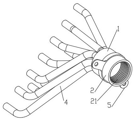
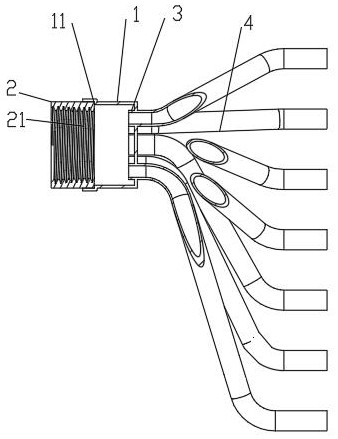
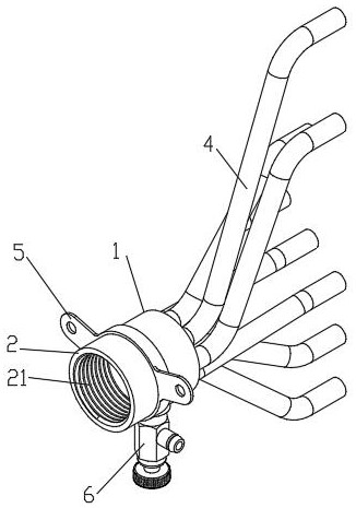
[0027] like Figures 1 to 10 It is a structural schematic diagram of the present invention, a new type of water flow distributor for fan coil units, which is characterized in that it includes a connected cavity structure 1 for distributing water flow or converging water flow and a connecting part 2 with openings at both ends. One end of the body structure 1 is open or provided with an end plate 12, and a number of shunt holes 3 are provided on the end wall or side wall of the other end. The opening of the cavity structure 1 or the end plate 12 is provided with a counterbore 11 for accommodating the connecting part 2 , one end of the connecting portion 2 is fixed in the counterbore 11 , and the branch pipe 4 is fixed at the branch hole 3 .
[0028] Specifically, this water flow distributor adopts a segmented design, one section is a cavity structure 1 with a larger inner diameter, which is used to better accommodate and distribute water flow, and the other section is a connection part 2 with a smaller diameter, which is used to connect with The water inlet or outlet of each circuit of the fan coil unit is connected. Compared with the integrally formed water flow distributor, this structure has a slightly smaller inner diameter of the connection part, and one end is fixed in the cavity structure, while the cavity structure The wall thickness of part 1 is thinner and the inner diameter is larger to better meet the needs of water flow, save the use of materials, and reduce costs on the premise of meeting functional requirements. In addition, the segmented main body design can reduce processing difficulty and improve processing efficiency, and the structural form of the connecting portion 2 can be selected according to needs. In addition, the distribution holes 3 are located on the end wall or the side wall, and more holes can be arranged to meet the quantity requirement of the distribution branch pipes 4 .
[0029] In this application, the counterbore 11 may be directly provided at the opening of the cavity structure 1 or on the end plate 12 of the cavity structure 1 , and the connecting part 2 is fixed in the counterbore 11 . like Figure 9 and 10 As shown, an end plate 12 is provided at one end of the cavity structure 1, so that the inner diameter of the cavity structure 1 is larger, which can better meet the requirement of uniform distribution of water flow.
[0030] According to another embodiment of the present invention, it further includes that the outer wall of the cavity structure 1 is provided with a fixed wing 5 , and the fixed wing 5 is provided with a through hole or a flange threaded hole. It is convenient to fix the whole water flow distributor more firmly on the fan coil unit.
[0031] According to another embodiment of the present invention, it further includes that, when the water flow distributor is used as a water collector, the outer wall of the cavity structure 1 is provided with a flange threaded hole, and is connected with an air release valve 6 for exhausting. When the fluid in the system has air and affects the heat exchange efficiency of the fan coil unit, the air release valve 6 can be opened to exhaust.
[0032] According to another embodiment of the present invention, it further includes that one end of the connecting part 2 is fixed in the counterbore 11 by welding. The welding process is simple and the connection is firm.
[0033] According to another embodiment of the present invention, it further includes that one end of the distribution branch pipe 4 is fixed in the distribution hole 3 of the cavity structure 1 by welding, and the distribution hole 3 is provided with a flange for increasing the contact surface with the welding material. The flanging increases the contact surface with the welding material, making the welding connection between the branch pipe and the cavity stronger and more secure.
[0034] According to another embodiment of the present invention, it further includes that the cross-sectional outer contours of the cavity structure 1 and the connecting portion 2 are circular, square or polygonal.
[0035] According to another embodiment of the present invention, it further includes that the inner wall or the outer wall of the connecting part 2 is provided with a connecting thread 21 or a quick-connect joint structure. To meet different connection needs. like Figures 1 to 4 is a schematic diagram of the internal thread; such as Figures 5 to 8 It is a schematic diagram of the external thread structure.
[0036] According to another embodiment of the present invention, it further includes that the distribution branch pipe 4 is bent, and the outer ends of the distribution branch pipe 4 are connected with the water inlet or outlet of each circuit of the fan coil unit. This effectively ensures the water distribution and collection of the distribution branch pipe 4 , and at the same time, the curved distribution branch pipe 4 can better save the arrangement space.
[0037] The above description is only illustrative, rather than restrictive, to the present invention. Those skilled in the art understand that many modifications, changes or the like can be made without departing from the spirit and scope defined by the appended claims. effect, but all will fall within the protection scope of the present invention.

PUM

no PUM

Description & Claims & Application Information

We can also present the details of the Description, Claims and Application information to help users get a comprehensive understanding of the technical details of the patent, such as background art, summary of invention, brief description of drawings, description of embodiments, and other original content. On the other hand, users can also determine the specific scope of protection of the technology through the list of claims; as well as understand the changes in the life cycle of the technology with the presentation of the patent timeline. Login to view more.

Similar technology patents

Union type single tube pass floating head heat exchanger

ActiveCN105823352AThe structure of the floating head is simplesave material
Owner:SINOPEC ENG +1

Punching technique for hypogynous metal bumper of heavy-duty car

InactiveCN101239369Asave materialReduce the number of mold sets
Owner:中国重汽集团济南技术中心有限公司

Cascading type rectifier used for SCR denitration device

Owner:CPI YUANDA ENVIRONMENTAL PROTECTION ENG +1

Classification and recommendation of technical efficacy words

  • save material
  • low cost

Plastic film

InactiveUS20140079938A1save materiallow density
Owner:MONDI CONSUMER PACKAGING TECH

Micro USB (universal serial bus) receptacle

Owner:ZHONGSHAN K MATE GENERAL ELECTRONICS

System and method for transmitting wireless digital service signals via power transmission lines

ActiveUS7929940B1reduce bandwidth requirementlow cost
Owner:NEXTEL COMMUNICATIONS

System and method for determination of position

InactiveUS20090149202A1low costreduce requirement
Owner:STEELE CHRISTIAN

Adaptive antenna optimization network

InactiveUS6961368B2low costminimal space
Owner:ERICSSON INC

Antenna device and method for attaching the same

ActiveUS20150138022A1low costimproved strength characteristic
Owner:NEC CORP
Why Eureka
Try Eureka