
Device for simulating hypersonic speed condensation process in spray pipe and diagnosis method

A hypersonic, coagulation process technology, used in measuring devices, machine/structural components testing, instruments, etc., can solve the problems of reducing the scanning frequency, increasing the output wavelength of the laser, complicated processing process, etc., to ensure uniformity, guarantee Variety, the effect of shortening the expansion time

Active Publication Date: 2021-11-16
UNIV OF SCI & TECH OF CHINA
View PDF5 Cites 0 Cited by
  • Summary
  • Abstract
  • Description
  • Claims
  • Application Information

AI Technical Summary

Problems solved by technology

However, when using TDLAS technology to measure the key parameters of the flow field, the method of multi-laser parallel measurement is often used. This method requires the use of multiple measurement channels, and at the same time cannot effectively synchronize the measurement results, and the processing process is very complicated.
However, the current baseline fitting method used in TDLAS signal processing requires a long baseline at both ends of the absorption signal. However, due to the limited output wavelength of the laser, under high temperature and high pressure conditions, the broadening of the absorption line is similar to the output wavelength of the laser. , the current baseline fitting method cannot obtain an effective baseline. At this time, the laser output wavelength can only be increased by reducing the scanning frequency, which limits the time resolution of the measurement to generally below 10kHz

Method used


Image

  • Device for simulating hypersonic speed condensation process in spray pipe and diagnosis method
  • Device for simulating hypersonic speed condensation process in spray pipe and diagnosis method
  • Device for simulating hypersonic speed condensation process in spray pipe and diagnosis method

Examples


Embodiment Construction

[0034] The following will clearly and completely describe the technical solutions in the embodiments of the present invention with reference to the accompanying drawings in the embodiments of the present invention. Obviously, the described embodiments are only some, not all, embodiments of the present invention. Based on the embodiments of the present invention, all other embodiments obtained by persons of ordinary skill in the art without making creative efforts belong to the protection scope of the present invention.

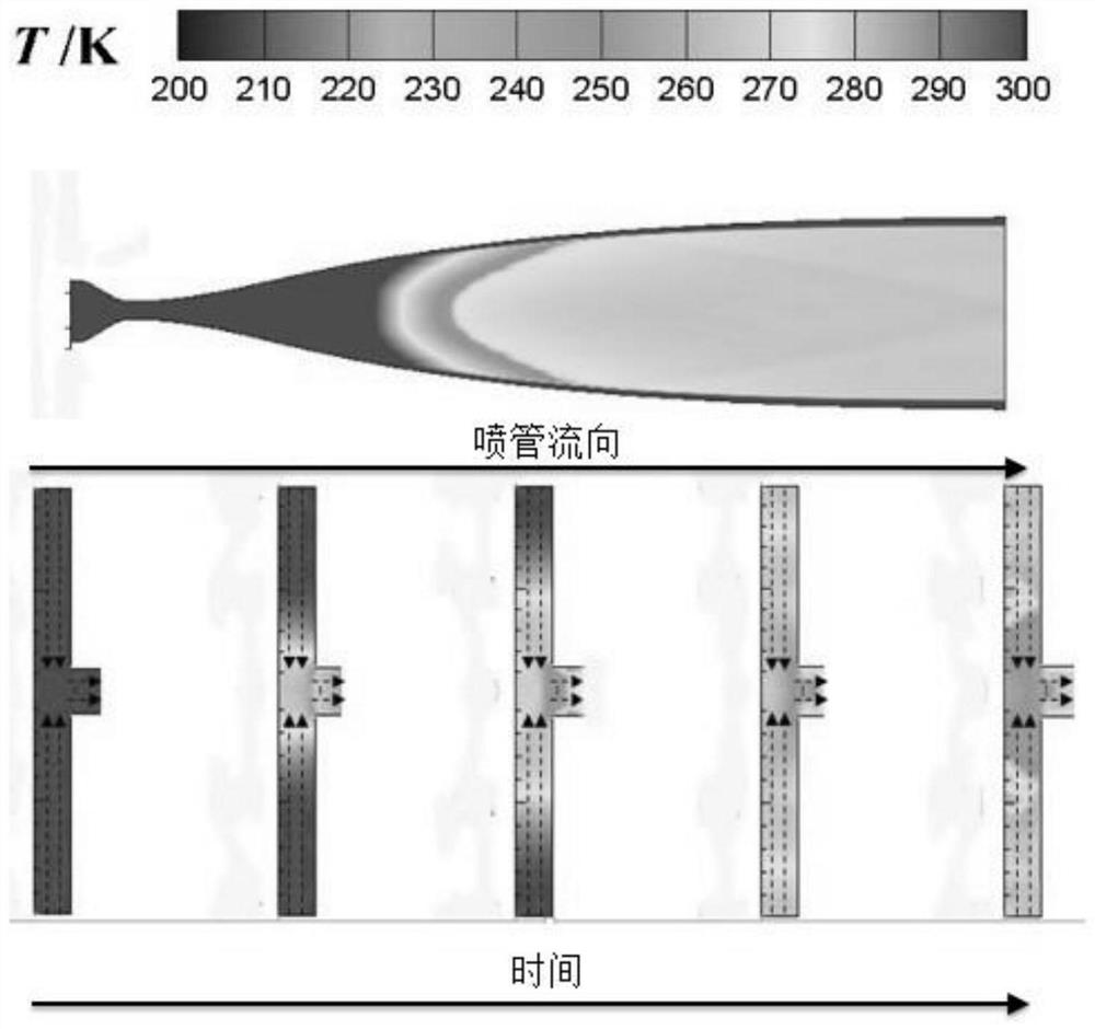
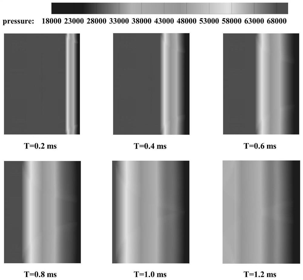
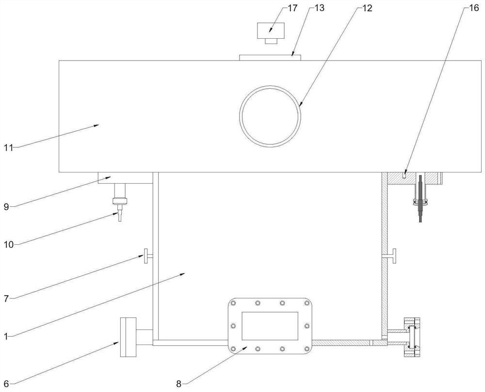
[0035] like image 3 and Figure 4 As shown, a device for simulating the hypersonic condensation process in the nozzle designed by the present invention includes a simulated nozzle device and a measurement system. The simulated nozzle device mainly includes a test section 1, a connection section 9, and a vacuum section 11, wherein the test section 1 and the connection section 9 are connected by the screw at the test section and the connection section threaded...


PUM


Abstract

The invention discloses a device for simulating a hypersonic speed condensation process in a spray pipe and a diagnosis method. The device comprises a simulation spray pipe device and a measurement system, the simulation spray pipe device comprises a test section (1), a connection section (9) and a vacuum section (11); and the measurement system comprises a TDLAS measuring system, a pressure measuring system and a high-speed photographing system. The device is based on the sparse wave principle, the sparse waves are reflected on the wall surface and the gas contact surfaces of the high-pressure section and the low-pressure section, so that the pressure at the position of a measuring point is continuously reduced, the degree of supercooling is increased, and substances are condensed, and the device ensures the uniformity of a flow field of a test section; and meanwhile, the hypersonic speed condensation process of the substance is realized in a relatively small time scale (less than 1ms). The measurement method is based on the TDLAS measurement principle, and adopts multi-laser signal coupling and a novel baseline fitting method, so that the measurement diversity is ensured, and the time resolution is 100kHz and above.

Description

technical field [0001] The invention relates to the field of hypersonic coagulation of substances, and particularly designs a device and a diagnostic method for simulating the hypersonic coagulation process in a nozzle. Background technique [0002] In a combustion heating wind tunnel, whether hydrogen fuel or hydrocarbon fuel is used, there is water vapor in the product. Before the product gas enters the wind tunnel test section through the equipment nozzle, the temperature drops due to the rapid expansion of the gas along the nozzle expansion section. , may cause rapid condensation of water vapor in the combustion products. At the same time, when the airflow passes through the compression surface of the tested engine, the temperature and pressure suddenly rise due to the shock wave compression, which may cause the condensed water droplets to re-evaporate and other phase transition phenomena. According to the existing literature, the condensation phase change of water vapo...

Claims


Application Information

Patent Timeline
Patent Type & Authority Applications(China)
IPC IPC(8): G01M9/08G01M9/06
CPCG01M9/08G01M9/06G01M9/065
Inventor 金熠黄生洪王新宝陈龙奎王浩楠李建斌
Owner UNIV OF SCI & TECH OF CHINA
Learn More