Auxiliary positioning method for unmanned aerial vehicle, system, storage medium and terminal equipment

An auxiliary positioning and UAV technology, applied in radio wave measurement systems, instruments, measurement devices, etc., can solve the problem of signal strength drop at the receiving end, and achieve the effect of improving the accuracy of acquisition

Pending Publication Date: 2021-11-16
GUANGZHOU UNIVERSITY
0 Cites 0 Cited by

AI-Extracted Technical Summary

Problems solved by technology

[0004] However, in actual situations, there are obstacles between the sending end and the receiving end, such as tall buildings, trees, et...

Method used

Above-mentioned unmanned aerial vehicle auxiliary positioning method obtains the receiving signal with noise by signal strength model; The described receiving signal input filter with noise is carried out filter processing, to eliminate the shadow noise in the described receiving signal; Pass cost The model performs iterative processing on the received signal with shadow noise removed to obtain the path fading factor and the distance between the transmitting end and the receiving end; according to the path fading factor and the distance between the transmitting end and the receiving end, the user is positioned. Compared with the prior art, the present invention can consider the influence of the shadow effect on the signal strength, and improve the acquisition accuracy of the path fading factor, so that the positioning accuracy of the user meets the actual application requirements.
In summary, the UAV-assisted positioning method, system, storage medium and terminal equipment provided by the embodiments of the present invention obtain a received signal with noise through a signal strength model; the received signal with noise is input into the filter performing filtering processing to eliminate shadow noise in the received signal; performing iterative processing on the received signal that eliminates shadow noise through a cost model to obtain the path fading factor and the distance between the transmitting end and the receiving end; according to the path fading factor and the distance between the transmitting end and the receiving end to locate the user. Compared with the prior art, the present invention can consider the influence of the shadow effect on the signal strength, and improve the acquisition accuracy of the path fading factor, so that the positioning accuracy of ...

Abstract

The invention relates to an auxiliary positioning method for an unmanned aerial vehicle. The method comprises the following steps: obtaining a receiving signal with noise through a signal intensity model; inputting the receiving signal with noise into a filter for filtering so as to eliminate shadow noise in the receiving signal; carrying out iterative processing on the receiving signal subjected to shadow noise elimination through a cost model so as to obtain a path fading factor and a distance between the transmitting end and the receiving end; and positioning the user according to the path fading factor and the distance between the transmitting end and the receiving end. According to the method, the influence of the shadow effect on the signal strength can be considered, and the acquisition precision of the path fading factor is improved, so that the positioning precision of the user meets the actual application requirement.

Application Domain

Using reradiation

Technology Topic

Shadow effectAerospace engineering +5

Image

  • Auxiliary positioning method for unmanned aerial vehicle, system, storage medium and terminal equipment
  • Auxiliary positioning method for unmanned aerial vehicle, system, storage medium and terminal equipment
  • Auxiliary positioning method for unmanned aerial vehicle, system, storage medium and terminal equipment

Examples

  • Experimental program(1)

Example Embodiment

[0050] The following will clearly and completely describe the technical solutions in the embodiments of the present invention with reference to the accompanying drawings in the embodiments of the present invention. Obviously, the described embodiments are only some, not all, embodiments of the present invention. Based on the embodiments of the present invention, all other embodiments obtained by persons of ordinary skill in the art without creative efforts fall within the protection scope of the present invention.
[0051] It should be noted that the numbering of the steps in the text is only for the convenience of explanation of the specific embodiments, and does not serve as a function of limiting the execution order of the steps. The method provided in this embodiment may be executed by a relevant server, and the description below takes the server as an execution subject as an example.
[0052] like Figure 1 to Figure 7 As shown, the UAV-assisted positioning method provided by the embodiment of the present invention, the method includes steps S11 to S14:
[0053] In step S11, a received signal with noise is obtained through a signal strength model.
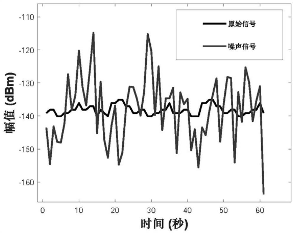
[0054]Specifically, assuming that there is a mobile user on the ground, and N drones are deployed in the air, the drone can locate the mobile user on the ground according to the signal strength. That is, the UAV is used as the transmitting end of the signal, and the mobile user is used as the receiving end of the signal. The signal strength received by the receiving end can be calculated through the signal strength model. Among them, for the graph of the original signal and the noisy signal, please refer to figure 2.
[0055] Further, the signal strength model is:
[0056]
[0057] in, is the transmission signal received by the user from the i-th anchor point, in dBm; is the strength of the transmitted signal; is a constant, which is the reference power at one meter from the transmitted signal; κ i is the path fading factor between the user and the i-th anchor point; d is the distance between the user and the i-th anchor point; is mean 0, variance σ 2 The shadow noise of is fitted with a normal distribution.
[0058] It can be understood that the received signal strength and the distance from the transmitting end to the receiving end can be obtained through the signal strength model. where the shadow noise and the estimate of κ and the shadow noise It will affect the positioning accuracy.
[0059] Step S12, inputting the received signal with noise into a filter for filtering processing, so as to eliminate shadow noise in the received signal.
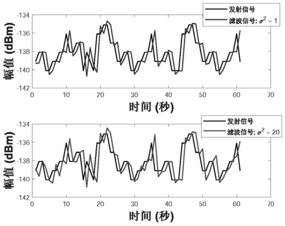
[0060] Specifically, because is an additive random process whose distribution is independent of κ and d, so The elimination of can be considered as an independent problem to solve. To this end, we design a filter based on the LMS algorithm to eliminate n, and the taps of this filter are trained by the training sequence. That is, the additive Gaussian white noise is eliminated through a weighted filter, and the shadow noise is transformed into a Gaussian random variable that obeys a uniform distribution, and its mean value is zero, and its variance is a certain number. For the graph of the original signal and the filtered signal, please refer to image 3.
[0061] see Figure 4 , the acquisition method of the filter includes:
[0062] Step S121, acquiring initialization parameters.
[0063] Wherein, the initialization parameters include the training sequence x, the subsequence x of x, the received signal with noise of a specific length M filter tap ω j , the number of filter taps L and the learning step size μ.
[0064] Step S122, starting from a certain element of the training sequence, taking a specific degree of filter taps as a subsequence.
[0065] Specifically, starting from the jth element of the training sequence χ, a subsequence x(j) of length L is taken, that is, x(j)=[x(j-L)]x(j-L+1)...x( j-1)] T ].
[0066] Step S123 , filtering the received signal with noise in the subsequence through the filter taps to obtain an output value.
[0067] Specifically, through ω j Filter x(j) to get an output value of
[0068] Step S124, updating the error value according to the output value, and updating the filter according to the error value and the learning step.
[0069] Specifically, the error value is The model of the filter is:
[0070] ω=ω j +2μe(j)x T (j)
[0071] Among them, ω j is the filter tap, μ is the learning step size, e(j) is the error value, x(j) is the subsequence, j is the element in the training sequence, and T is the matrix transpose.
[0072] Step S13 , iteratively processing the received signal with shadow noise removed through a cost model to obtain the path fading factor and the distance between the transmitting end and the receiving end.
[0073] Specifically, in wireless communication, the path attenuation factor κ is a variable value. In fact, the value of κ changes with the environment, and the value of κ will affect the positioning accuracy. Therefore, this application uses a cost model to estimate κ and d. The idea of ​​the algorithm is to fix d first, iterate on κ until κ reaches a certain precision, and update the value of κ; then fix κ, iterate on d until d reaches a certain precision, and update the value of d. After a certain number of iterations, κ and d with high precision are obtained. For the mean square error plot of its positioning see Figure 5.
[0074] see Figure 6 to Figure 7 , the method for iteratively processing the received signal for eliminating shadow noise through a cost model includes:
[0075] Step S131, initialize the path fading factor and the distance between the transmitting end and the receiving end.
[0076] Step S132, perform iterative training on the initialized path fading factor and the distance between the transmitting end and the receiving end through the cost model.
[0077] Step S133 , when the first search accuracy of the path fading factor and the second search accuracy of the distance between the transmitting end and the receiving end tend to converge, updating the cost model.
[0078] Specifically, initialize the path fading factor and the distance between the transmitter and the receiver, and use the trained filter ω to eliminate shadow noise The initialized path fading factor is iteratively trained through the cost model until Then update the κ value in the cost function, namely The distance between the initialized transmitter and receiver is iteratively trained through the cost model until Then update the d value in the cost function, ie
[0079] Wherein, the cost model is:
[0080]
[0081] Among them, P t For the transmitted signal, P r is the received signal, κ is the path fading factor, d is the distance between the transmitting end and the receiving end, is the shadow noise, ω is the filter, K is the number of iterations, ε κ is the first search accuracy, ε d is the second search precision.
[0082] It can be understood that through separate iterations for κ and d, the problem of low accuracy of iteration results due to multiple local optimal solutions due to non-convex problems when solving d is avoided.
[0083] Step S14, locating the user according to the path fading factor and the distance between the transmitting end and the receiving end.
[0084] As mentioned above, by considering the influence of the shadow effect in the signal propagation process, and positioning the user through the path fading factor with high accuracy and the distance between the transmitting end and the receiving end, the satisfaction of the user positioning experience is improved.
[0085] The above-mentioned UAV-assisted positioning method obtains a received signal with noise through a signal strength model; filters the received signal with noise into a filter to eliminate shadow noise in the received signal; The received signal of shadow noise is iteratively processed to obtain the path fading factor and the distance between the transmitting end and the receiving end; and the user is positioned according to the path fading factor and the distance between the transmitting end and the receiving end. Compared with the prior art, the present invention can consider the influence of the shadow effect on the signal strength, and improve the acquisition accuracy of the path fading factor, so that the positioning accuracy of the user meets the actual application requirements.
[0086] It should be understood that although the various steps in the above flow chart are displayed sequentially according to the arrows, these steps are not necessarily executed sequentially in the order indicated by the arrows. Unless otherwise specified herein, there is no strict order restriction on the execution of these steps, and these steps can be executed in other orders. Moreover, at least some of the steps in the above flowchart may include multiple sub-steps or multiple stages, these sub-steps or stages are not necessarily executed at the same time, but may be executed at different times, the sub-steps or stages The order of execution is not necessarily performed sequentially, but may be performed alternately or alternately with at least a part of other steps or sub-steps or stages of other steps.
[0087] like Figure 8 As shown, it is a structural block diagram of a UAV auxiliary positioning system provided by the present invention, and the system includes:
[0088] The noise obtaining module 21 is configured to obtain a received signal with noise through a signal strength model.
[0089] Wherein, the signal strength model is:
[0090]
[0091] in, is the transmission signal received by the user from the i-th anchor point, in dBm; is the strength of the transmitted signal; is a constant, which is the reference power at one meter from the transmitted signal; κ i is the path fading factor between the user and the i-th anchor point; d is the distance between the user and the i-th anchor point; is mean 0, variance σ 2 The shadow noise of is fitted with a normal distribution.
[0092] The filter processing module 22 is configured to input the received signal with noise into a filter for filter processing, so as to eliminate shadow noise in the received signal.
[0093] Specifically, the acquisition of the filter is,
[0094] Acquire initialization parameters; wherein, the initialization parameters include training sequences, specific lengths of received signals with noise, filter taps, number of filter taps, and learning steps;
[0095] Starting from a certain element of the training sequence, taking a specific degree of filter taps as a subsequence;
[0096] Filtering the received signal with noise in the subsequence through the filter taps to obtain an output value;
[0097] An error value is updated according to the output value, and the filter is updated according to the error value and the learning step size.
[0098] Further, the model of the filter is:
[0099] ω=ω j +2μe(j)x T (j)
[0100] Among them, ω j is the filter tap, μ is the learning step size, e(j) is the error value, x(j) is the subsequence, j is the element in the training sequence, and T is the matrix transpose.
[0101]The iterative training module 23 is configured to use a cost model to iteratively process the received signal with shadow noise removed, so as to obtain the path fading factor and the distance between the transmitting end and the receiving end.
[0102] The iterative training module 23 is specifically used for,
[0103] Initialize the path fading factor and the distance between the transmitter and the receiver;
[0104] performing iterative training on the initialized path fading factor and the distance between the transmitting end and the receiving end through the cost model;
[0105] When the first search accuracy of the path fading factor and the second search accuracy of the distance between the transmitting end and the receiving end tend to converge, the cost model is updated.
[0106] The cost model is:
[0107]
[0108] Among them, P t For the transmitted signal, P r is the received signal, κ is the path fading factor, d is the distance between the transmitting end and the receiving end, is the shadow noise, ω is the filter, K is the number of iterations, ε κ is the first search accuracy, ε d is the second search precision.
[0109] The user positioning module 24 is configured to locate the user according to the path fading factor and the distance between the transmitting end and the receiving end.
[0110] The UAV-assisted positioning system provided by the embodiment of the present invention obtains a received signal with noise through a signal strength model; the received signal with noise is input to a filter for filtering processing to eliminate shadow noise in the received signal ; Perform iterative processing on the received signal with shadow noise removed through a cost model to obtain the path fading factor and the distance between the transmitting end and the receiving end; locate the user according to the path fading factor and the distance between the transmitting end and the receiving end. Compared with the prior art, the present invention can consider the influence of the shadow effect on the signal strength, and improve the acquisition accuracy of the path fading factor, so that the positioning accuracy of the user meets the actual application requirements.
[0111] An embodiment of the present invention also provides a computer-readable storage medium, the computer-readable storage medium includes a stored computer program; wherein, when the computer program is running, the computer program controls the device where the computer-readable storage medium is located to execute the above-mentioned The described UAV-assisted positioning method.
[0112] The embodiment of the present invention also provides a terminal device, see Figure 9 Shown is a structural block diagram of a preferred embodiment of a terminal device provided by the present invention. The terminal device includes a processor 10, a memory 20, and is stored in the memory 20 and is configured to be controlled by the processor 10. A computer program is executed, and the processor 10 implements the UAV-assisted positioning method as described above when executing the computer program.
[0113] Preferably, the computer program can be divided into one or more modules/units (such as computer program 1, computer program 2, ...), and the one or more modules/units are stored in the stored in the memory 20 and executed by the processor 10 to complete the present invention. The one or more modules/units may be a series of computer program instruction segments capable of accomplishing specific functions, and the instruction segments are used to describe the execution process of the computer program in the terminal device.
[0114] The processor 10 may be a central processing unit (Central Processing Unit, CPU), and may also be other general-purpose processors, a digital signal processor (Digital Signal Processor, DSP), an application specific integrated circuit (Application Specific Integrated Circuit, ASIC), Ready-made programmable gate array (Field-Programmable Gate Array, FPGA) or other programmable logic devices, discrete gate or transistor logic devices, discrete hardware components, etc., the general-purpose processor can be a microprocessor, or the processor 10 can also be It is any conventional processor, and the processor 10 is the control center of the terminal equipment, using various interfaces and lines to connect various parts of the terminal equipment.
[0115] The memory 20 mainly includes a program storage area and a data storage area, wherein the program storage area can store an operating system, an application program required by at least one function, etc., and the data storage area can store related data and the like. In addition, the memory 20 can be a high-speed random access memory, or a non-volatile memory, such as a plug-in hard disk, a smart memory card (Smart Media Card, SMC), a secure digital (Secure Digital, SD) card and a flash memory Card (Flash Card), etc., or the memory 20 may also be other volatile solid-state memory devices.
[0116] It should be noted that the above-mentioned terminal device may include, but not limited to, a processor and a memory. Those skilled in the art can understand that, Figure 9 The structural block diagram is only an example of a terminal device, and does not constitute a limitation on the terminal device, and may include more or less components than those shown in the figure, or combine certain components, or different components.
[0117] In summary, the UAV-assisted positioning method, system, storage medium, and terminal equipment provided by the embodiments of the present invention obtain a received signal with noise through a signal strength model; input the received signal with noise into a filter for filtering processing , to eliminate shadow noise in the received signal; iteratively process the received signal that eliminates shadow noise through a cost model to obtain the path fading factor and the distance between the transmitting end and the receiving end; according to the path fading factor and the transmitting end The distance from the receiving end is used to locate the user. Compared with the prior art, the present invention can consider the influence of the shadow effect on the signal strength, and improve the acquisition accuracy of the path fading factor, so that the positioning accuracy of the user meets the actual application requirements.
[0118] The above is only a preferred embodiment of the present invention, and it should be pointed out that for those of ordinary skill in the art, without departing from the technical principle of the present invention, some improvements and modifications can also be made. It should also be regarded as the protection scope of the present invention.

PUM

no PUM

Description & Claims & Application Information

We can also present the details of the Description, Claims and Application information to help users get a comprehensive understanding of the technical details of the patent, such as background art, summary of invention, brief description of drawings, description of embodiments, and other original content. On the other hand, users can also determine the specific scope of protection of the technology through the list of claims; as well as understand the changes in the life cycle of the technology with the presentation of the patent timeline. Login to view more.

Similar technology patents

Comprehensive detection system for aero-engine vibration device

PendingCN113063600AImprove acquisition accuracyExtended service life
Owner:中国人民解放军海军航空大学青岛校区

Classification and recommendation of technical efficacy words

  • Improve Acquisition Accuracy

Comprehensive detection system for aero-engine vibration device

PendingCN113063600AImprove acquisition accuracyExtended service life
Owner:中国人民解放军海军航空大学青岛校区
Why Eureka
Try Eureka