Printing and dyeing dust remover

A dust collector and dust collection technology, applied in the field of printing and dyeing, can solve the problems of polluting the surrounding environment and physical damage of operators, and achieve the effects of improving the workshop environment, increasing vibration, and protecting physical health.

Inactive Publication Date: 2021-11-19
张宗宇
View PDF1 Cites 0 Cited by
  • Summary
  • Abstract
  • Description
  • Claims
  • Application Information

AI Technical Summary

Problems solved by technology

[0006] Aiming at the deficiencies of the prior art, the present invention provides a printing and dyeing dust collector, which solves the problem that in the traditional printing and dyeing process, the waste gas generated contains harmful gases such as fluff and dust, which are directly scattered in the workshop, pollute the surrounding environment, and are operated at the same time The problem of causing great damage to the operator's body after inhalation

Method used


Image

  • Printing and dyeing dust remover
  • Printing and dyeing dust remover
  • Printing and dyeing dust remover

Examples


Embodiment 1

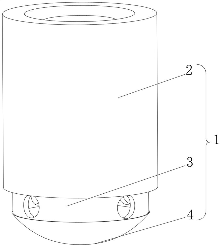
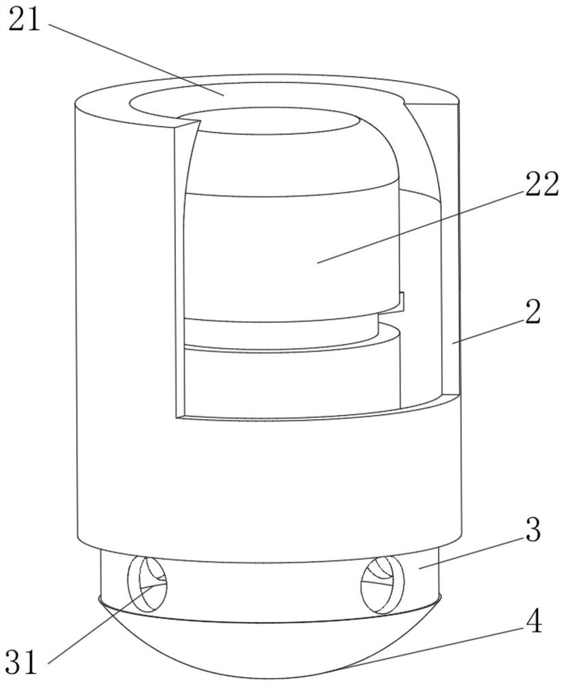
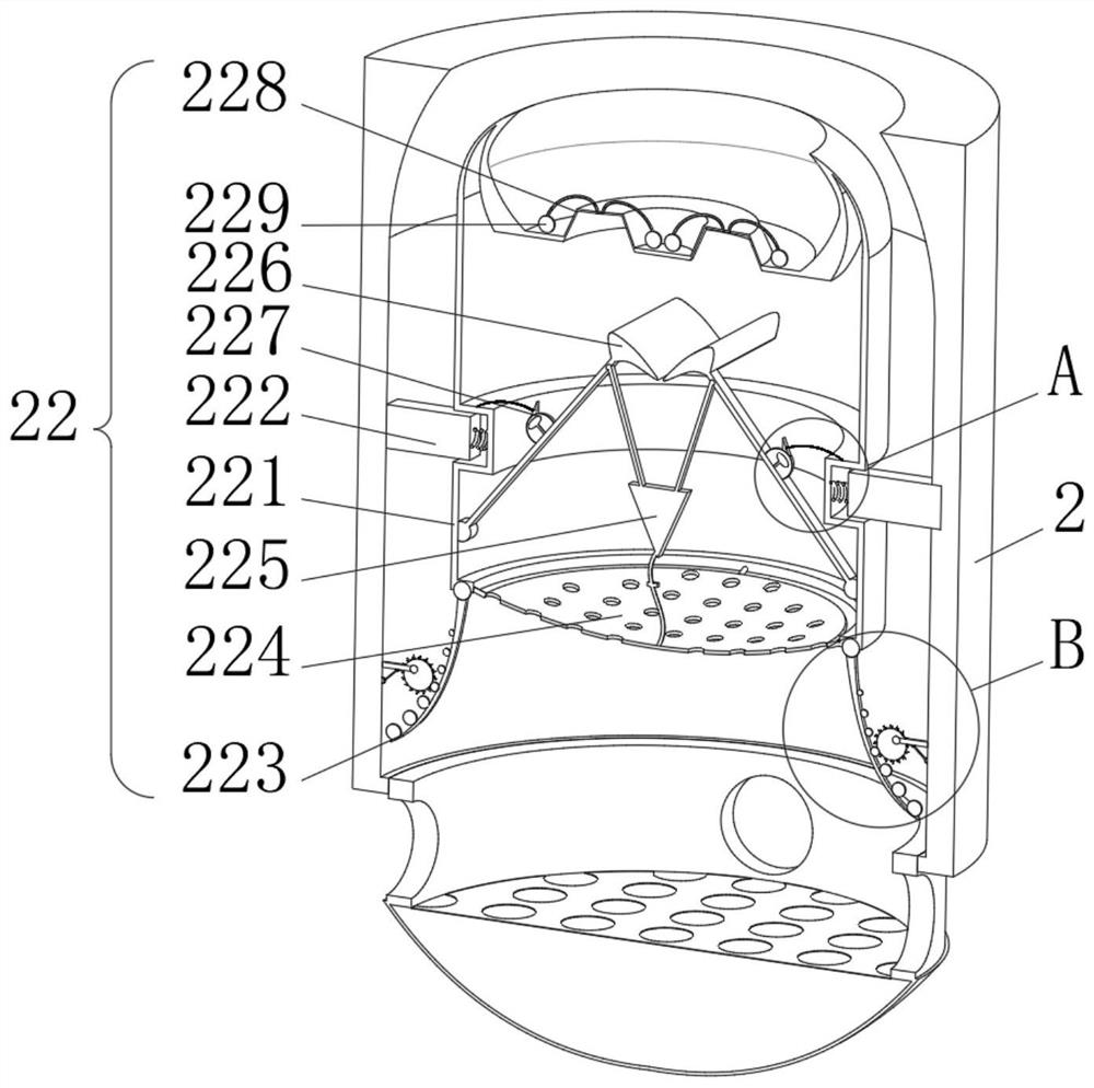
[0035] see Figure 1-3 , the present invention provides a technical solution: a printing and dyeing dust collector, including a printing and dyeing dust collector body 1 composed of a dust removal shell 2, an air intake plate 3 and a dust collection shell 4, the bottom of the dust removal shell 2 is fixed to the top of the air intake plate 3 connection, the bottom of the air intake plate 3 is threadedly connected to the top of the dust collection case 4, the top of the dust removal case 2 is provided with an air outlet 21, the interior of the dust removal case 2 is provided with a filter mechanism 22, and the interior of the air intake plate 3 is provided with an air intake port 31, the filter mechanism 22 includes a filter housing 221, the inside of the filter housing 221 is slidably connected to a limit block 222 by a spring, the side of the limit block 222 away from the filter shell 221 is slidably connected to the inside of the dust removal shell 2, and the bottom of the fi...

Embodiment 2

[0041] see Figure 1-5 On the basis of Embodiment 1, the present invention provides a technical solution: the shaker 223 includes a shaker plate 2231, the top of the shaker plate 2231 is rotationally connected with the bottom of the filter housing 221 through a reset piece, and the right side of the shaker plate 2231 is fixedly connected Rocking ball 2232 is arranged, and the right side of shaking ball 2232 is provided with cam 2233, and the outside of cam 2233 is fixedly connected with projection 2234, and the inside of projection 2234 is fixedly connected with the inside of dust removal case 2 by rotating rod.

[0042] The counterweight 227 comprises a counterweight ring 2271, the bottom of the counterweight ring 2271 is fixedly connected to the top of the windshield 226, the inside of the counterweight ring 2271 is provided with a water storage bag 2272, and the bottom of the water storage bag 2272 is connected to the shield by an elastic rod. The inside of the air plate 22...

Embodiment 3

[0045] see Figure 1-6 , On the basis of Embodiment 1 and Embodiment 2, the present invention provides a technical solution: the suction device 225 includes a suction frame 2251, and the interior of the suction frame 2251 is respectively provided with a first magnetic block 2252 and a second magnetic block 2253, the right side of the first magnetic block 2252 is fixedly connected to the left side of the second magnetic block 2253 through a string.

[0046] The suction frame 2251 is fixedly connected with an elastic ring 2254, and the side of the elastic ring 2254 away from the suction frame 2251 is fixedly connected with a folding plate 2255, and the outside of the folding plate 2255 is slidingly connected with the outside of the rotating rod. The side is rotationally connected with the bottom end of the rotating rod through the rotating seat, and the right side of the second magnetic block 2253 is rotationally connected with the bottom end of the rotating rod through the rota...


PUM


Abstract

The invention discloses a printing and dyeing dust remover comprising a printing and dyeing dust remover body composed of a dust removal shell, an air inlet plate and a dust collection shell; the bottom of the dust removal shell is fixedly connected with the top of the air inlet plate, the bottom of the air inlet plate is in threaded connection with the top of the dust collection shell, and an air outlet is formed in the top of the dust removal shell; a filtering mechanism is arranged in the dust removal shell; an air inlet is formed in the air inlet plate; the filtering mechanism comprises a filtering shell, the interior of the filtering shell is slidably connected with a limiting block through a spring, and the side, away from the filtering shell, of the limiting block is slidably connected with the interior of the dust removal shell. The invention relates to the technical field of printing and dyeing. According to the printing and dyeing dust remover, the problems that in a traditional printing and dyeing process, generated waste gas contains cloth velvet, dust and other harmful gas, the waste gas directly drifts in a workshop and pollutes the surrounding environment, and meanwhile the body of an operator is greatly damaged after the waste gas is inhaled into the body of the operator are solved.

Description

technical field [0001] The invention relates to the technical field of printing and dyeing, in particular to a dust collector for printing and dyeing. Background technique [0002] Printing and dyeing is also called dyeing and finishing. It is a processing method, and it is also a general term for pretreatment, dyeing, printing, finishing, washing, etc.; the undergraduate dyeing and finishing major has now been incorporated into the light chemical engineering major; as early as the Neolithic Age six or seven thousand years ago, Our ancestors were able to dye sackcloth red with hematite powder. The primitive tribes living in the Nomuhong area of ​​the Qaidam Basin in Qinghai can dye wool into yellow, red, brown, blue and other colors, and weave woolen cloth with colored stripes. During the Shang and Zhou dynasties, dyeing technology continued to improve. There are full-time officials "dye people" in the palace handicraft workshops to "hand dye grass" and manage the dyeing ...

Claims


Application Information

Patent Timeline
Patent Type & Authority Applications(China)
IPC IPC(8): B01D46/00B01D46/10B01D50/00B01D53/78
CPCB01D53/78B01D46/103B01D46/10B01D46/0052B01D2258/02
Inventor 张宗宇
Owner 张宗宇
Why Eureka
Try Eureka