
Battery swap station

A technology for power swapping stations and power swapping equipment, which is applied in the field of swapping stations, can solve the problems of affecting the service life, occupying a large area, and not being able to apply and promote the swapping stations in a wide range, and achieve the effect of a compact overall structure and a small footprint

Pending Publication Date: 2021-11-19
AULTON NEW ENERGY AUTOMOTIVE TECHNOLOGY GROUP
View PDF0 Cites 0 Cited by
  • Summary
  • Abstract
  • Description
  • Claims
  • Application Information

AI Technical Summary

Problems solved by technology

[0003] In the prior art, the battery swap station generally includes a battery swap bin and a charging bin. In actual use, both the swap bin and the charging bin are fixedly installed on the ground to facilitate battery pick-up and replacement. However, for larger battery packs The replacement stations for commercial vehicles occupy a large area, so that this type of replacement stations cannot be widely used and promoted, and most of the replacement equipment in the replacement stations are exposed to the external environment, and the components of the replacement equipment are easily damaged. Corrosion or damage, affecting service life

Method used


Image

  • Battery swap station
  • Battery swap station
  • Battery swap station

Examples


Embodiment 1

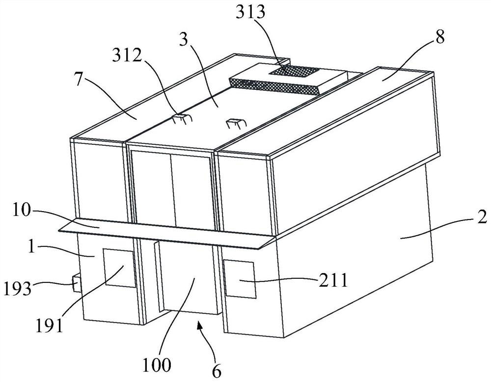
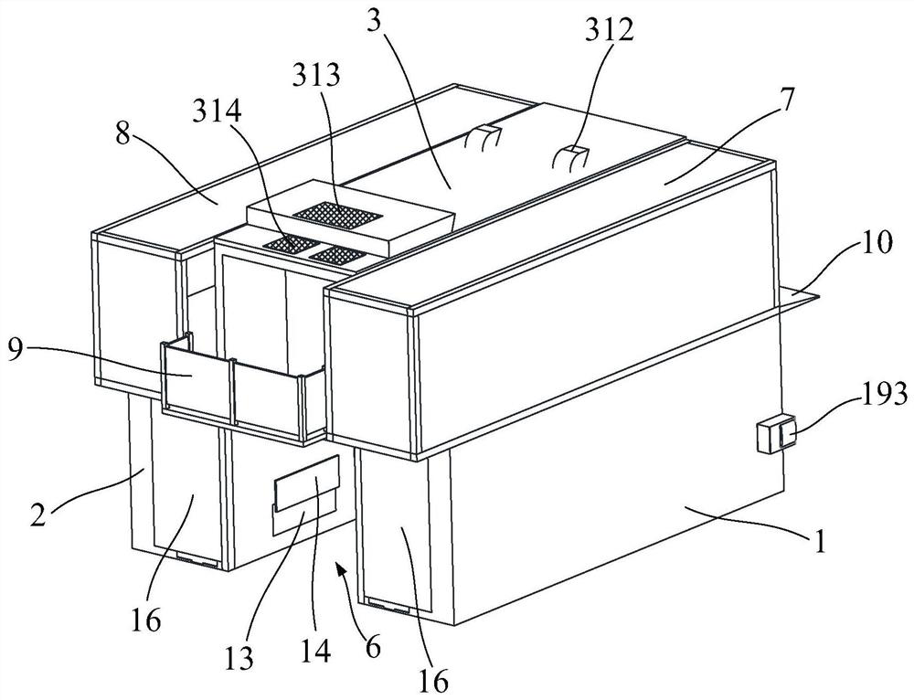
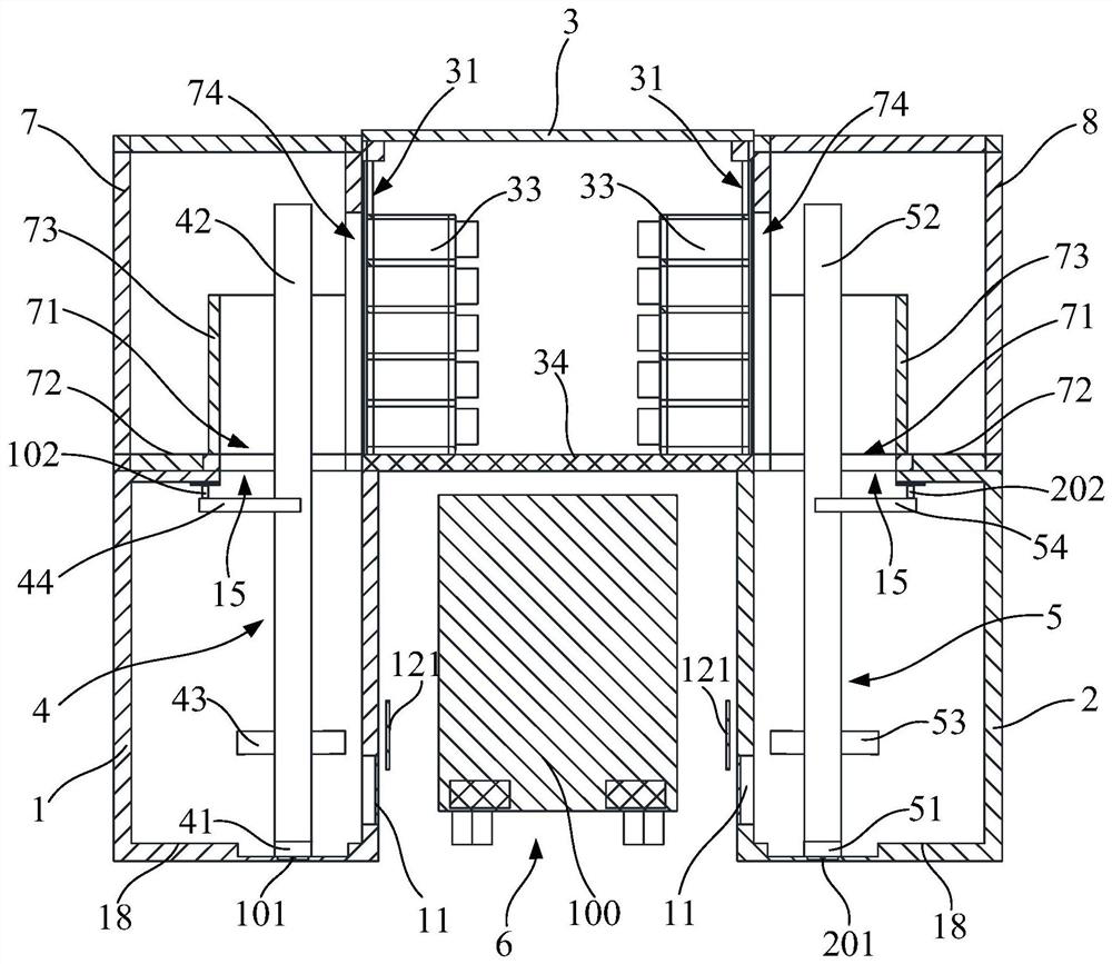
[0101] The invention provides a power station for replacing battery packs on electric vehicles. like Figure 1 to Figure 3 As shown, the power exchange station includes a first power exchange warehouse 1, a second power exchange warehouse 2, a charging warehouse 3, a first power exchange equipment 4 and a second power exchange equipment 5, and the first power exchange warehouse 1 and the second power exchange warehouse A driveway 6 is formed between the compartments 2, and the driveway 6 is used to park the electric vehicle 100; the charging compartment 3 is used to charge and discharge the battery pack replaced from the electric vehicle 100, the charging compartment 3 is located above the driveway 6, and the charging compartment 3 The warehouse 3 is respectively connected to the first battery exchange warehouse 1 and the second battery exchange warehouse 2; the first battery exchange equipment 4 and the second battery exchange equipment 5 are respectively arranged in the firs...

Embodiment 2

[0153] The structure of the power station in Embodiment 2 is roughly the same as that in Embodiment 1, the difference is that:

[0154] like Figure 19 to Figure 20 As shown, the switching station also includes an exit canopy 20 installed on the end face of the charging bin 3 , and the exit canopy 20 is located above the exit of the driving passage 6 . The exit canopy 20 is used to block the exit of the driving passage 6 when it rains, so that rainwater will not enter the driving passage 6 .

[0155] This substation can also not be provided with a maintenance balcony, and the top of the entrance canopy 10 is set as the first walking passage 30, and the top of the export canopy 20 is set as the second walking passage 40, the first walking passage 30, the second walking passage The channel 40 extends to the charging bin 3 , the first upper swap bin 7 and the second upper swap bin 8 . A first transition door 50 is provided between the upper maintenance channel 72 of the first u...

Embodiment 3

[0158] The structure of the power station in Embodiment 3 is roughly the same as that in Embodiment 1, the difference is that:

[0159] like Figure 21 As shown, the power exchange station uses the first top canopy 80 to replace the first upper battery exchange warehouse 7 in Embodiment 1, and uses the second top canopy 90 to replace the second upper battery exchange warehouse 8 in Embodiment 1. The first The top canopy 80 and the second top canopy 90 extend from the top of the charging compartment 3 to both sides, the first top canopy 80 is located above the first battery exchange compartment 1, and the second top canopy 90 is located at the second battery exchange compartment 2 above.

[0160] The first top canopy 80 and the second top canopy 90 can also play the function of covering the open space between the first battery exchange compartment 1, the second battery exchange compartment 2 and the charging compartment 3, and the canopy type The design and manufacture are si...


PUM


Abstract

The invention discloses a battery swap station. The station comprises a first battery swap bin, a second battery swap bin, a charging bin, a first battery swap device and a second battery swap device, wherein a driving channel is formed between the first battery swap bin and the second battery swap bin, and the driving channel is used for parking an electric vehicle; the charging bin is used for charging and discharging a battery pack replaced from the electric vehicle, the charging bin is located above the driving channel, and the charging bin is connected with the first battery swap bin and the second battery swap bin; the first battery swap device and the second battery swap device are arranged in the first battery swap bin and the second battery swap bin correspondingly, and the first battery swap device and the second battery swap device are used for replacing battery packs between the electric automobiles on the charging bin and the driving channel. According to the battery swap station, the charging bin is arranged above the driving channel, the first battery swap bin and the second battery swap bin are arranged on the two sides of the driving channel, the battery swap requirement of an electric vehicle with battery swap on the two sides can be met, and the battery swap station is compact in overall structure and small in occupied area.

Description

technical field [0001] The invention relates to a substation. Background technique [0002] With the supply pressure and exhaust pollution brought about by the consumption of traditional fossil energy, the development of traditional fuel vehicles has entered a period of stagnation. Favored by the prospect of green energy, electric vehicles have shown a blowout development in recent years due to their advantages in energy saving and environmental protection. However, due to the short board of battery charging time, electric vehicles have prompted the emergence of quick-change electric vehicles, that is, to quickly replace the battery pack on the electric vehicle, remove the battery pack that has lost power and install a fully charged battery pack. The weight of the battery pack of electric vehicles is very heavy due to the demand for cruising range. Therefore, the replacement of the battery pack needs to rely on proprietary equipment. Therefore, the swap station emerged as a...

Claims


Application Information

Patent Timeline
Patent Type & Authority Applications(China)
IPC IPC(8): B60L53/80
CPCY02T10/70Y02T10/7072B60L53/80
Inventor 黎明文超王胜德
Owner AULTON NEW ENERGY AUTOMOTIVE TECHNOLOGY GROUP
Learn More