Terminal anchoring wire clamp mechanism of high-iron copper alloy contact wire

A contact wire and copper alloy technology, which is applied in the field of terminal anchoring clamp mechanism of high-iron copper alloy contact wire, can solve problems such as the gap between splint and contact wire, loose contact wire, and affecting the stability of contact wire fixation, etc., and achieves a wide range of applications , the effect of improving stability

Inactive Publication Date: 2021-11-19
JIANGSU MEILIN COPPER
View PDF0 Cites 0 Cited by
  • Summary
  • Abstract
  • Description
  • Claims
  • Application Information

AI Technical Summary

Problems solved by technology

[0004] The purpose of the present invention is to solve the problem that when the terminal anchoring structure of the existing high-iron-copper alloy contact wire in the prior art is in use, the contact wire is prone to thermal expansion and contraction under the influence of the external temperature. , the contact wire will shrink, which will easily cause a gap between the splint and the contact wire, resulting in loosening of the contact wire, thus affecting the fixation stability of the contact wire. A high-iron-copper alloy contact wire is proposed Terminal anchor clamp mechanism

Method used


Image

  • Terminal anchoring wire clamp mechanism of high-iron copper alloy contact wire
  • Terminal anchoring wire clamp mechanism of high-iron copper alloy contact wire
  • Terminal anchoring wire clamp mechanism of high-iron copper alloy contact wire

Examples


Embodiment 1

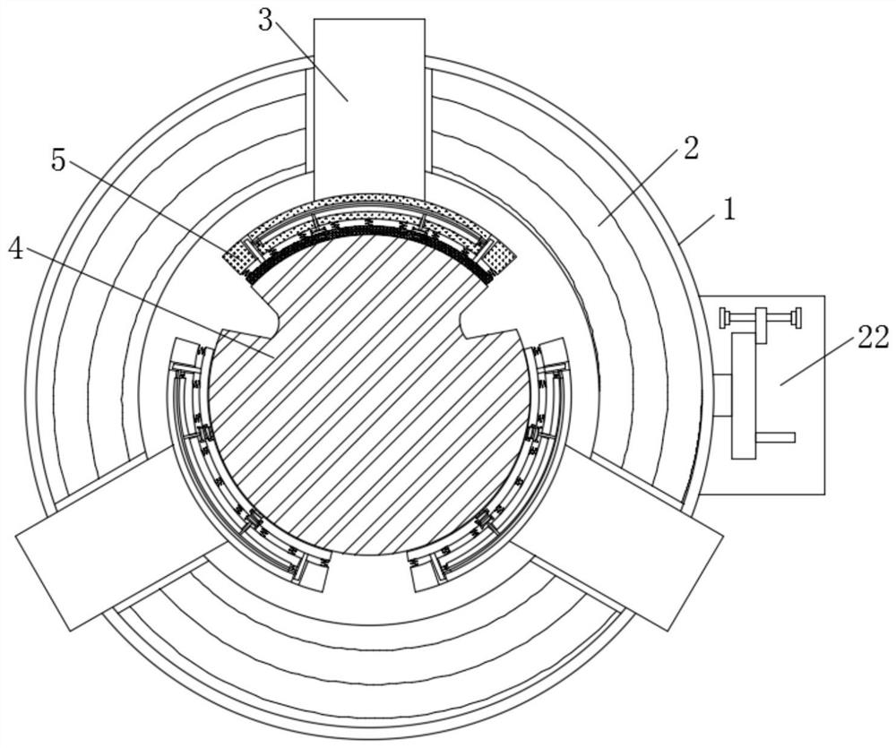
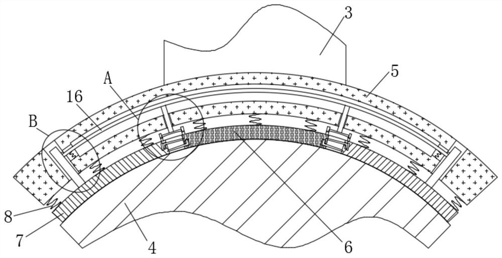
[0031] refer to Figure 1-6 , a terminal anchoring clamp mechanism for high-iron copper alloy contact wires, including a housing 1, a three-jaw chuck 2 is fixedly installed on the housing 1, a contact wire body 4 runs through the middle of the three-jaw chuck 2, and the three-jaw chuck 2. Several sliders 3 are installed on the front end, and the end of the slider 3 close to the contact line body 4 is fixedly equipped with a fixed splint 5, and the middle part of the side of the fixed splint 5 close to the contact line body 4 is provided with a movable splint 6. Two movable splints 7 are symmetrically arranged on both sides of splint one 6, and one end of movable splint one 6 and movable splint two 7 close to the contact wire body 4 is fitted with the contact wire body 4, and the fixed splint 5 is close to the contact wire body 4 One end is provided with a plurality of springs 8, and the other ends of the springs 8 are respectively fixedly connected to movable splint 1 6 and mo...

Embodiment 2

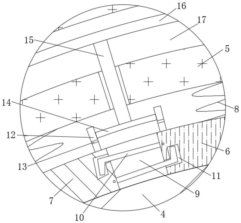
[0034] refer to Figure 1-6 , in this embodiment, it is basically the same as Embodiment 1, and more optimally, a through groove 9 is provided at the connection between the two ends of the movable splint 6 and the movable splint 2 7, and there are two through groove 1 9 The adjustment clamp 10, the ends of the adjustment clamps 10 on both sides that are far away from each other are respectively hinged with the movable splint one 6 and the movable splint two 7, and the one end of the movable splint one 6 and the movable splint two 7 that are close to each other corresponds to the adjustment card The rods 10 are all provided with a card slot 11, and the adjustment bar 10 is movably connected to the card slot 11;

[0035] During use, the set through groove one 9, the adjustment lever 10 and the draw groove 11 are convenient to make the bending angle between the movable splint one 6 and the movable splint two 7 carry out self-adaptive adjustment according to the actual size of the...

Embodiment 3

[0037] refer to Figure 1-6, in this embodiment, it is basically the same as Embodiment 1, and more optimally, a sealing plate 12 is fixedly installed on the end of the movable splint 6 and the movable splint 7 away from the contact wire body 4, and there are several openings on the sealing plate 12. The through hole 13, the sealing plate 12 is inserted with a piston 14, the end of the piston 14 away from the contact wire body 4 is fixedly connected with a connecting rod 15, and the end of the connecting rod 15 away from the contact wire body 4 is fixedly installed with a connecting piece 16, Corresponding connecting piece 16 and connecting rod 15 inside described fixing splint 5 are all provided with through groove 2 17, and connecting rod 15 and connecting piece 16 are movably connected fixing splint 5, and described connecting piece 16 is close to one end both sides of contact line body 4. A spring two 18 is fixedly connected, and the other end of the spring two 18 is fixed...


PUM


Abstract

The invention discloses a terminal anchoring wire clamp mechanism for a high-iron copper alloy contact wire, which comprises a shell, a three-jaw chuck is fixedly mounted on the shell, a contact wire body penetrates through the middle part in the three-jaw chuck, a plurality of sliding blocks are mounted at the front end of the three-jaw chuck, and fixed clamping plates are fixedly mounted at ends, close to the contact wire body, of the sliding blocks; a movable clamping plate I is arranged in the middle of one side, close to the contact wire body, of each fixed clamping plate; and movable clamping plates II are symmetrically arranged on two sides of each movable clamping plate I. When the terminal anchoring wire clamp mechanism is used, the fixed clamping plates and springs I are matched with the fixed clamping plates, the movable clamping plates I and the movable clamping plates II, so that the fixed clamping plates, the movable clamping plates I and the movable clamping plates II can synchronously stretch out and draw back when the contact wire body expands with heat and contracts with cold, and the phenomenon that the contact wire body contracts with cold due to cold temperature in winter is avoided; therefore, the contact wire body is loosened from the fixed clamping plates, the movable clamping plates I and the movable clamping plates II, and the fixing stability of the contact wire body is improved.

Description

technical field [0001] The invention relates to the technical field of high-speed iron contact wires, in particular to a terminal anchoring clamp mechanism for high-iron copper alloy contact wires. Background technique [0002] The contact wire mainly refers to the contact wire used for the electrified railway catenary. Its structural characteristics are copper, copper-silver alloy, high-strength copper-silver alloy, copper-tin alloy, copper-magnesium alloy, high-strength copper-magnesium alloy, etc. Railway catenary needs. Various contact wires such as copper, copper-silver alloy, high-strength copper-silver alloy, copper-tin alloy, copper-magnesium alloy, and high-strength copper-magnesium alloy can be provided in accordance with the Ministry of Railways TB / T2809. [0003] When the terminal anchoring structure of the existing high-iron-copper alloy contact wire is in use, the contact wire is prone to thermal expansion and contraction under the influence of the external te...

Claims


Application Information

Patent Timeline
Patent Type & Authority Applications(China)
IPC IPC(8): B60M1/26B60M1/20
Inventor 邵云林翟金勇李小武
Owner JIANGSU MEILIN COPPER
Why Eureka
Try Eureka