Pile top pre-piercing type cushion structure of building composite foundation
A composite foundation and cushion layer technology, which is applied in the direction of foundation structure engineering, construction, protection devices, etc., can solve the problems of soil loss between the cushion layer and piles, poor cushioning and vibration absorption, and affecting the stability of building foundations, etc., to achieve Improve the anti-seepage ability, improve the stability, and improve the effect of anti-seepage performance
- Summary
- Abstract
- Description
- Claims
- Application Information
AI Technical Summary
Problems solved by technology
Method used
Image

Examples
Embodiment 1
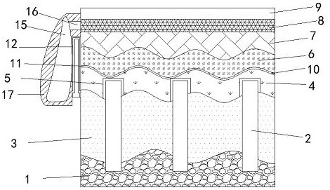
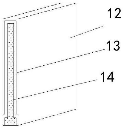
[0023] First embodiment, such as figure 1 --3, according to the pre-piercing composite foundation pile top mattress layer structure of a building formula embodiment of the present invention, including a rock, the rock is provided with a top layer of sand 3, the inner layer of sand 3 2 is provided with rigid pile, above the sand layer 3 is provided cushion, 2 to the top of the rigid post to said penetrating cushion, cushion provided above the base floor 7, the 7 is provided above the base floor concrete layer 9, the base steel surface layer 8 is provided between the concrete layers 7 and 9, the side reinforcement layer 8 is provided with the connecting plate 16, the connecting plate 16 of the other retaining member 15 is provided at one end, the outer surface of the retaining member 15 is provided with a retaining housing 17, retaining the inner housing 17 is provided between the mattress layer 12 water-repellent layer, the water-repellent layer 12 13 is provided with a support mem...
Embodiment 2
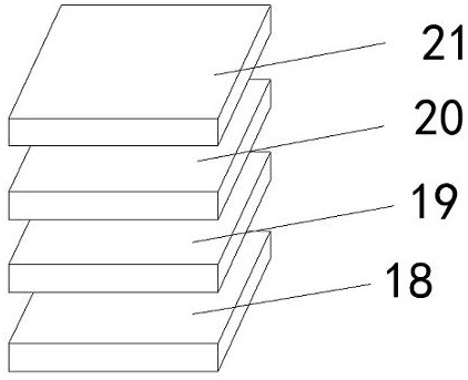
[0024] According to the second embodiment, including a rock, the rock is provided with a top layer of sand 3, the sand layer 3 features two rigid pile, above the sand layer 3 is provided Cushion, said rigid piles 2 penetrating into the top of the mattress layer, is provided above the base floor cushion 7, 7 above the base floor concrete layer 9 is provided, the base surface of the concrete layer 7 of 9 8 is provided between the reinforcement layer, the reinforcement layer 8 is provided with a side web 16, the other end of the connecting plate 16 is provided with a retaining member 15, the outer surface of the retaining member 15 of the housing 17 is provided with retaining the breakwater is provided between the housing 17 and the water-repellent layer 12 of the mattress layer, the water-repellent layer 12 is provided inside the support member 13, the support member 13 is provided inside the heat insulating layer 14, the mattress 4 comprises a rigid cushion cushion cushion 6 flexib...
Embodiment 3
[0025] Embodiment 3 comprises a rock, the rock is provided with a top layer of sand 3, the sand layer 3 features two rigid pile, above the sand layer 3 is provided Cushion, said rigid piles 2 penetrating into the top of the mattress layer, is provided above the base floor cushion 7, 7 above the base floor concrete layer 9 is provided, the base surface of the concrete layer 7 of 9 8 is provided between the reinforcement layer, the reinforcement layer 8 is provided with a side web 16, the other end of the connecting plate 16 is provided with a retaining member 15, the outer surface of the retaining member 15 of the housing 17 is provided with retaining the breakwater is provided between the housing 17 and the water-repellent layer 12 of the mattress layer, the water-repellent layer 12 is provided inside the support member 13, the support member 13 is provided inside the heat insulating layer 14, the rigid 4 is provided with the flexible cushion cushion impermeable barrier 6 between ...
PUM
| Property | Measurement | Unit |
|---|---|---|
| Thickness | aaaaa | aaaaa |
| Thickness | aaaaa | aaaaa |
| Thickness | aaaaa | aaaaa |
Abstract
Description
Claims
Application Information
 - R&D
- Intellectual Property
- Life Sciences
- Materials
- Tech Scout
- Unparalleled Data Quality
- Higher Quality Content
- 60% Fewer Hallucinations
Browse by: Latest US Patents, China's latest patents, Technical Efficacy Thesaurus, Application Domain, Technology Topic, Popular Technical Reports.
© 2025 PatSnap. All rights reserved.Legal|Privacy policy|Modern Slavery Act Transparency Statement|Sitemap|About US| Contact US: help@patsnap.com